background image

R

epair

P 3 / 9

< 1 > Lubrication 

< 2 > Disassembling ball bearing at the top of arm ( Only for the arms of 9mm and 13mm width)

( Only for the arms of 9mm and 13mm width)

< 3 > Assembling ball bearing at the top of arm

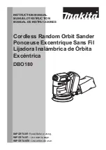
Apply a little MAKITA grease N No.2 to the following portions marked with black triangle to protect parts 
and machine from unusual abrasion.  See Fig. 1.

Pulley cover

Bracket

The sliding 
portion

Arm cover

Came lever

Arm installing
side

Ball bearing

Pin 4

Arm 

Ball bearing

Flat washer

Flat washer

Pin 4

Arm 

No.1R032 Bearing Setting Plate

Put arm on No.1R032 "bearing setting plate", and keep the arm horizontal by supporting it 
with No. 1R033 "bearing setting plate". And set No.1R278 "round bar for arbor" on pin 4.  See Fig. 2.

Press  No.1R278 "round bar for arbor" with arbor press. So, ball bearing and 2 pcs. of flat washers can be
disassembled from arm.  See Fig. 2A.   

No.1R033 Bearing 
                  Setting Plate

No.1R033 Bearing 
                  Setting Plate

1R278. Round bar  
             for arbor

Fig. 1

Fig. 2

Fig. 2A

Ball bearing

Flat washers

1R278. Round bar for arbor

1R278. Round bar
             for arbor

Pin 4

Align the holes of flat washers with the hole of ball bearing by applying 1R278. "round bar for arbor" as illustrated
in Fig. 3.
After putting pin 4 on the aligned holes, press the 1R278. "round bar for arbor" put on pin 4, with arbor press 
as illustrated in Fig. 3 A.

Fig. 3 A

Fig. 3

< Note > As for arm of 6mm width, ball bearing and axis are integral part of arm, which can not be removed. 

No.1R032 Bearing Setting Plate

Summary of Contents for 9032

Page 1: ...put W 110 120 220 230 240 50 60 50 60 50 60 50 60 50 60 4 8 4 4 2 4 2 3 2 2 Current A Specification Standard equipment Optional accessories Note The standard equipment for the tool shown may differ fr...

Page 2: ...2 9031 710 500 350 500 550 533 21 520 20 1 2 455 17 7 8 533 21 533 21 Width mm Length mm Max sanding length mm Max sanding length 110mm 4 5 16 Adjustment of arm angle Tension roller s diameter of stan...

Page 3: ...ith No 1R033 bearing setting plate And set No 1R278 round bar for arbor on pin 4 See Fig 2 Press No 1R278 round bar for arbor with arbor press So ball bearing and 2 pcs of flat washers can be disassem...

Page 4: ...g 4 B Arm holder Arm Arm cover Arm Arm cover Compression spring 6 Arm tensioner Arm holder Set cam lever on on lock position 1 Set cam lever to lock position by pushing it in the direction of arrow as...

Page 5: ...section can be separated from motor unit See Fig 6 2 Take off bracket together with armature by unscrewing tapping screws 4 x 25 as illustrated in Fig 6 A 3 Separate driving roller from armature shaf...

Page 6: ...DW Fig 6 C 7 Assembling driving roller and armature 1 Assemble ball bearing 608DDW to the armature shaft of fan side and assemble insulation washer and ball bearing 627DDW to the armature shaft of com...

Page 7: ...een assembled to motor housing as illustrated in Fig 7 C Bracket Armature Tapping screws 4 x 25 Motor housing Fig 7 C Tapping screws M4 x 18 1 Take off tapping screws 4 x 18 and inserting screwdriver...

Page 8: ...4 Controller 1 2 Switch Field Color index of lead wires Black White Orange Noise suppressor Power supply cord 1 2 3 4 Controller 1 2 Switch Field Noise suppressor Power supply cord Choke coil Field In...

Page 9: ...Wiring diagram P 9 9 Controller Pass the lead wires of power supply cords and the same ones of controller through the space of another side of control dial as illustrated below...

Reviews: