


75
Temperature Tests
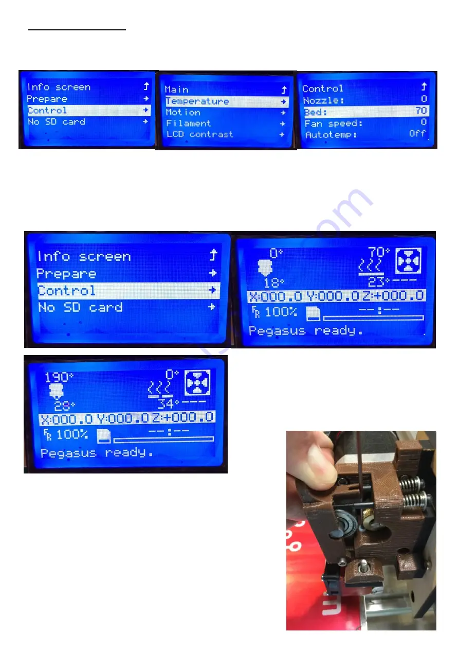
Next you will test that the heat bed and hot end heat up, select the “Control”, “Temperature”,
“Bed” then turn the knob until the bed is set to 70. Then go back to “Control”, “Main” then
“Info Screen”, you should see the heat bed temp set to 70c and you should see the temp start
to rise, while the temp is low check to see if you can feel the temp of the heat bed rising.
While the heat bed is heating the hot end temp should stay low and shouldn’t rise in temp
drastically. Once you know the heat bed is heating look at your hot end fan and verify that it
is turning, if it is not make sure your hot end fan is connected directly to the power supply or
the Power input of your ramps board.
Go back to “Control”, “Temperature”, change
the bed temp to 0 then change the hot end
temperature to 190c. Now go back to the
“Info Screen” and verify that the hot end temp
is rising.
Now you
can install
filament
into the
extruder, pull back on the Guidler with your thumb, thread
the filament past the MK7 Drive gear and into the PTFE
tube, continue to push the filament until the filament stops
at the nozzle then release the Guidler. Now is a good time
to clean up the wiring of your printer, use the zip ties to
keep them out of the way and neat. Make sure you leave
enough slack so the extruder can move all the way right
and left, the heat bed can move forware and back and the
X axis can move up and down.
Summary of Contents for Pegasus 12
Page 1: ...Updated 6 19 17 ...
Page 5: ...5 ...
Page 6: ...6 ...
Page 19: ...19 Installl the two Z motors into the Z mounts using 4 M3x6mm bolts on each motor ...
Page 41: ...41 Belts 4 x Zip Ties 2 x M3x25mm Bolts 2 x M3 Nylon Lock Nut 1 x GT2 Belt ...
Page 47: ...47 For the Endstops follow the endstop guide by clicking on the Picture below ...
Page 48: ...48 This page intentionally left blank ...
Page 49: ...49 Optional LCD 1 x Wood LCD Mount 4 x M3x25mm Bolt 4 x M3 Lock nuts 1 x LCD Interface ...
Page 52: ...52 Then install the LCD using the 3 bolts ...
Page 63: ...63 Next plug in the Z Motors Now plug in the Y Motor ...
Page 69: ...This page intentionally left blank ...
Page 70: ...This page intentionally left blank ...
Page 71: ...This page intentionally left blank ...
Page 72: ......