Makerfarm Pegasus 12 Instructions Manual Download Page 27

27 

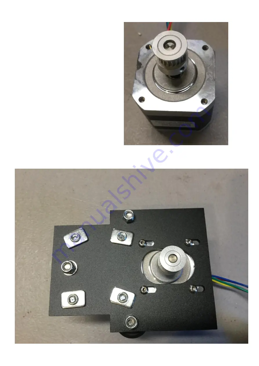
Install the GT2 Gear onto the Motor 
using the set screw, make sure the set 
screw hits the flat spot of the motor 
shaft. 


Flip the metal piece back over, install 
the motor using the 4 M3x6mm bolts, 
but leave the bolts some what loose at 
this time.  Have your motor wires come out of the side of the X Motor Bracket. 

Summary of Contents for Pegasus 12

Page 1: ...Updated 6 19 17 ...

Page 2: ...S BEEN ADVISED OF THE POSSIBLITY OF SUCH DAMAGES MFI S TOTAL LIABLITY TO CUSTOMER FROM ALL CAUSES OF ACTION AND UNDER ALL THEORIES OF LIABILITY WILL BE LIMITED TO THE AMOUNTS PAID TO MFI BY CUSTOMER THESE LIMITATIONS SHALL APPLY NOTWITHSTANDING ANY FAILURE OF ESSENTIAL PURPOSE OF ANY LIMITED REMEDY THE REMEDIES UNDER THIS LIMITED WARRANTY ARE CUSTOMER S SOLE AND EXCLUSIVE REMEDIES 7 Return Merchan...

Page 3: ...30 Metal X Idler Assembly Pgs 31 33 X Carriage Pgs 34 40 X Axis Pgs 41 43 Belts Pgs 44 46 Heat Bed Pgs 47 48 Endstops Pgs 49 52 LCD Installation Pg 53 E3D Hot End Assembly Pgs 54 Extruder Assembly Pgs 55 57 Z Rods Pgs 58 65 RAMPS Install Wiring Diagram Pgs 66 72 Wiring your Power supply Pgs 73 76 Software Firmware First Prints Pg 77 Wire Management Pgs 78 80 Pronterface Troubleshooting Guide Downl...

Page 4: ...ut it to the size you need Inside the USA Lowes or Home Depot For the Power Supply Insulation and Hairspray see the links at the bottom of the 12 Pegasus Page here http www makerfarm com index php 3d printer kits 12 pegasus kit html You may also want some filament to print with after you have built your printer Makerfarm com does sell filament and we would recommend using our filament or another h...

Page 5: ...5 ...

Page 6: ...6 ...

Page 7: ...his build guide to finish your build Frame Kit Version 1 has 10 Cast Corner Brackets with Nubs 4 Cast Corner Brackets without Nubs and 32 Hidden Corner Brackets FRAME KIT VERSION 1 Build Guide Frame Kit Version 2 has one kit with 35 Cast Corner Brackets with Nubs 4 Cast Corner Brackets without Nubs and 7 Hidden Corner Brackets FRAME KIT VERSION 2 Build Guide ...

Page 8: ...en use 2 without nubs 4 x Cast Corner Brackets without Nubs 4 x M5x8mm Bolts 3 x Motor Mounts 1 x M5x12mm Bolt 1 x T Slot Nut If you have 16 20x40 extrusions instead of 14 the following then follow pages 12 13 and 14 2 20x40mm Aluminum Extrusions 8 x Cast Corner Brackets without Nubs 2 x Cast Corner Brackets with Nubs Shown by the red circle in the photo below if none of your brackets have nubs th...

Page 9: ... position with a Red Circle You will adjust the actually placement later Now install 2 Cast Corner Brackets without Nubs and one Motor Mount on the bottom back of the frame using the previously installed M5x8mm Bolts You will adjust the actually placement later Now Install a Motor Mount of the right side of the printer make sure you use the slot on the far left of the motor bracket ...

Page 10: ...side of the printer make sure you use the slot on the far left of the motor bracket Next using the Extrusion and M5 bolts install the extrusion into the cast corner brackets Also install the M5x12mm bolt and T Slot nut onto the right extrusion ...

Page 11: ...xtrusion to the Cast Corner Brackets in the front of the machine also Make sure the bottom of the Extrusion is aligned with the bottom of the cast corner bracket on all 4 brackets otherwise your Y axis will not be flat ...

Page 12: ...t the actually placement later Now install 4 Cast Corner Brackets and one Motor Mount on the bottom back of the frame using the previously installed M5x8mm Bolts You will adjust the actually placement later Now Install a Motor Mount of the right side of the printer make sure you use the slot on the far left of the motor bracket ...

Page 13: ...ter make sure you use the slot on the far left of the motor bracket Next using the Extrusion M5 bolts and T Slot nuts install the extrusion into the cast corner brackets Also install the M5x12mm bolt and T Slot nut onto the right extrusion Shown by red arrow ...

Page 14: ...ackets in the front of the machine also This picture will show how the underside of the extrusion will look Make sure the bottom of the Extrusion is aligned with the top of the front and back extrusion pieces otherwise your Y axis will not be flat ...

Page 15: ... GT2 Gear and Set Screws 1 set of wood Y belt Mount 2 x Aluminum Spacers 2 x Eccentric Spacers 4 x M5x30mm Bolts 4 x M5 Nylon Lock Nut 4 x Delrin Idlers 1 x M3x25mm bolt 1 x M3x16mm bolt 3 x M3 Nylon Lock Nut 1 x Endstop 1 x Zip Tie 1 x Wood Endstop Mount 12 x M3x6mm Bolts ...

Page 16: ...o start install a GT2 gear onto a motor as shown below make sure to align one of the set screws with the flat spot on the Motor Using the Wood Endstop mount and a zip tie install the endstop as shown below ...

Page 17: ...t is 214mm away from the inside of the extrusion as shown below then move the extrusion in between the motor and side of the frame so its 78mm from the inside of the extrusion as shown below Next install the Motor with the GT2 gear using 4 of the M3x6mm bolts ...

Page 18: ...own below Adjust the two Z motor mounts so the surface the Z motor contacts is 55mm above the extrusion as shown Tighten the Z motor mount in place make sure the mount is not tilted This should let you just barely squeeze the motor into the mount ...

Page 19: ...19 Installl the two Z motors into the Z mounts using 4 M3x6mm bolts on each motor ...

Page 20: ... the M3x16mm Bolt and nut shown by the blue arrow in a hole 20mm to the right to allow for the thicker extrusion you may need to drill a new hole if your kit didn t ship with the wider Y extrusion Install the 4 M5x30mm bolts in the 4 larger holes as shown by the Red and Green Arrows then install an Aluminum Spacer on the bolts with the Red arrows and an eccentric spacer on the ones with the Green ...

Page 21: ...to each and tighten them down Tighten them just enough so the Delrin Idler doesn t wobble but the delrin can still turn Install the M3x25mm bolt into the center of the Mount shown by the Blue Arrow Get the Y belt Mount wood pieces and install the Piece into one of the A shaped pieces as shown below ...

Page 22: ...22 Now install the other A wood piece onto the wood piece then install it into the Aluminum Heat Bed Mount and tighten it down with the M3 bolt and a Nylon Lock nut ...

Page 23: ...he Right Extrusion Shown with the Green Arrow to the Right of the machine so all the Delrin Wheels ride in the left and right extrusions When the Right Extrusion contacts both Delrin Wheels you can tighten down the Right Extrusion Now move the heat bed mount back and forth make sure it turns freely then pull up and push down on each corner to see if there is any play If there is you can either pul...

Page 24: ...x Nema 17 Motor 1 x Gt2 Gear with Set Screw 4 x M3x6mm Bolts M3x8mm bolt and M3 Washer can also be used 3 x Delrin Idlers 1 x Eccentric Spacer 2 x Aluminum Spacers 3 x M5 Nylon Lock Nut 3 x M5x30mm Bolts 4 x M5x8mm Bolts 4 x T Slot Nuts 1 x M5 Washer not shown ...

Page 25: ...all a T Slot Nut on each of the 4 bolts Get 3 M5x30mm bolts and install a a Delrin Idler on all 3 then an aluminum spacer on two and an eccentric spacer on the other Install 4 M5x8mm bolts in to the Metal from the back then install a T Slot Nut on each of the 4 bolts ...

Page 26: ...rs and aluminum spacers on the side closest to where the Motor mounts then the one with the eccentric spacer on the left Flip the Metal plate back over install a M5 washer on the bolt that has the eccentric spacer then install a Nylon M5 Lock Nut on the 3 Bolts and tighten ...

Page 27: ...crew make sure the set screw hits the flat spot of the motor shaft Flip the metal piece back over install the motor using the 4 M3x6mm bolts but leave the bolts some what loose at this time Have your motor wires come out of the side of the X Motor Bracket ...

Page 28: ...Idler Wood Metal parts Pictured Below 3 x Pre Assembled Delrin Idler s Black Wheel 2 x MR125 Bearings 2 x M5 Washers 4 x M5x30mm Bolts 3 x M5 Nylon Locknuts 1 x M5 Nut Regular 4 x M5x8mm Bolts 2 x Aluminum Standoff 1 x Eccentric Spacer 4 x T Slot Nuts ...

Page 29: ...stall 4 of the M5x8mm bolts from the back side then flip the metal piece over and install the 4 T Slot nuts leaving them loose Next flip the X idler over and install 3 M5x30mm bolts into the holes as shown below ...

Page 30: ... install a delrin idler on each bolt and last install and tighten an m5 Nylon Lock nut Last you will assemble the Belt idler you will assemble it starting with an M5x30mm bolt then the rectangular wood piece an M5 Washer Two MR125zz Bearings another M5 washer the wooden washer and last a regular M5 nut ...

Page 31: ... parts 1 X Carriage Metal part Pictured Below 2 x M3x16mm Bolt 2 x M3 Nuts 3 x Pre Assembled Delrin Idler s Black Wheels 3 x M5x30mm Bolts 3 x M5 Nylon Locknuts Not Shown 1 x Aluminum Standoff 2 x Eccentric Spacer 2 x M3 Nylon Lock Nuts ...

Page 32: ...mm bolts as shown then install the Aluminum Spacer on the bottom bolt and the two eccentric spacers on the top two bolts Push the eccentric spacer into the metal and turn them so the notch is on the top Install Delrin Idlers on to the 3 bolts then a M5 Nylon Lock nut onto each bolt tighten the nuts but make sure the Delrin Idlers still turn freely ...

Page 33: ...33 Last Install the two M3x16mm Bolts and regular M3 nuts as shown tighten them down Then loosly install the Nylon Lock nuts on the M3 bolts you will remove them later to install the X Belt ...

Page 34: ...rusions 6 x M5x12mm Bolt 6 x T Slot Nuts 2 x MR125xx Bearings 2 x M5 Washers 1 x M5x30mm Bolt 1 x Regular M5 Nut Slide the two Extrusions onto the T Slot nuts on the X Motor Bracket push the extrusions away from each other inbetween the two T Slot nuts then tighten the bolts down your Extrusions should now be parallel to each other Slide the X Carriage onto the extrusion as shown below ...

Page 35: ...he back of the Extrusion as shown by the Green Arrow Leave the X idler loose Install Two T Slot Nuts into the Extrusion by the X Idler Bracket as shown by the Red Arrows Below then install the Adjustable Z endstop piece with a M5x12mm bolt and T Slot nut by the X motor bracket as shown by the Blue Arrow Last Install the Belt Idler onto the two T Slots using two M5x12mm long bolts The Belt Idler bo...

Page 36: ...36 Now slide the X axis down onto the Frame as shown below Since your X idler bolts are loose you can adjust the placement of the X idler to allow the X axis to slide onto the extrusion ...

Page 37: ...tric spacer on the X motor until you can see that all 3 delrin wheels on the X motor contact the extrusion Now tighten the Eccentric spacer on the X Idler side so all 3 delrin wheels contact the extrusion then tighten down all the bolts holding the X idler and Belt idler to the extrusion ...

Page 38: ...Z nut trap hole with the motor shaft on the X Motor Side then tighten down the bolts holding the Z nut trap to the extrusion Repeat the process for the Z Nut trap on the X Idler side before tightening down the bolts ...

Page 39: ...e the Heat Bed Mount to the front of the machine align the Y Belt idler with the wooden mount as shown then tighten down the bracket to the extrusion with the red arrow in the picture below then with an M5x30mm bolt install in between the two brackets a washer 2 MR125zz bearings another washer then tighten the M5x30mm bolt with an M5 regular nut last tighten the bracket with the blue arrow as show...

Page 40: ... everything tight After that you can flip the frame upside down so it looks like the picture below move the two extrusions so they are 140mm from the inside of the back extrusion then tighten the hidden corner brackets down Hidden corner brackets are all shown with blue arrows Next move the cast corner brackets down so you can connect them to the m5x8mm bolts you installed earlier See Red Arrows T...

Page 41: ...41 Belts 4 x Zip Ties 2 x M3x25mm Bolts 2 x M3 Nylon Lock Nut 1 x GT2 Belt ...

Page 42: ...otor around the GT2 Gear then back to the wooden mount Loop the other end making sure that the belt will be tight when you install it into the wooden mount then zip tie the loop and install the loop to the wooden mount using the other M3 bolt and Nylon Lock nut If you need to adjust the tension of the belt you can adjust the Y belt bearings in the front of the machine by moving them as far to the ...

Page 43: ...you X motor is pulled as far to the center of the printer as possible then loop the other end and install a zip tie before installing it on the other m3x16mm bolt Install M3 Lock nuts on the M3x16mm bolts use needle nose pliers to tighten the Nylon Lock Nuts At this time you can also adjust the Eccentric Spacer on the X carriage so all 3 wheels contact the Aluminum Extrusion Now pull the X motor t...

Page 44: ...acers Get the thermistor for your heat bed and if it hasn t already been taped to the bottom of the heat bed use kapton tape to tape it to the bottom so the glass bead is in the center of the bed Your kapton tape will not be as wide as the kapton tape shown so you will use more strips of tape ...

Page 45: ... 12 Laser Cut Wood spacers or 4 Springs over the 4 holes in the corner of the heat bed mount as shown in the two pictures below New kits will come with just the wood spacers instead of springs for better print quality ...

Page 46: ...46 Install your Insulation Fire Blanket on the heat bed mount then put the heat bed on top then install 4 bolts through the corners last install an M3 Nylon Lock nut onto each bolt and tighten them down ...

Page 47: ...47 For the Endstops follow the endstop guide by clicking on the Picture below ...

Page 48: ...48 This page intentionally left blank ...

Page 49: ...49 Optional LCD 1 x Wood LCD Mount 4 x M3x25mm Bolt 4 x M3 Lock nuts 1 x LCD Interface ...

Page 50: ...d spacers and put them on the 4 holes shown below Next get 2 more of the wood spacers and install them inbetween the two PCB boards on the LCD on the top two holes Do not install a spacer on the bottom holes of the PCB s ...

Page 51: ... 4 M3 Nylon Lock nuts on the bolts make sure the two on top are tight but don t tighten the bottom two to much or or the LCD will flex Install the Two ribbon cables Connect one cable to EXP1 on the LCD and EXP1 on the Smart Adapter then the other cable to both EXP2 Ports Align the LCD with the 3 previously installed M5x12mm bolts in the top right front corner of the frame as shown below ...

Page 52: ...52 Then install the LCD using the 3 bolts ...

Page 53: ...53 E3d Lite6 Hot End Gather the following parts 1 x Hot End Kit E3D Lite6 Assembly E3D v6 Assembly Your e3d Fan will connect directly to your power supply Black fan wire to v and red fan wire to v ...

Page 54: ...54 Extruder Click on the image of the Extruder you have to open the build guide for that Extruder ...

Page 55: ...Z Coupler Tubes Thread the M5 nuts onto the threaded rods about half way if the nut won t easily thread onto the threaded rod try the other end of the threaded rod Next Lift the X axis up push the threaded rods through the printed Z nut trap and seat the M5 nut in the printed piece repeat for the other side ...

Page 56: ...ould now have the threaded rod meeting the motor shaft half of the way into the clear tubing as shown in the bottom right picture Repeat the process for the other Z motor Your X axis should now be sitting on the M5 nuts on the threaded rods If the X axis is not parallel to the heat bed you can hold onto one threaded rod to prevent it from turning and turn the other rod ...

Page 57: ...why you have glass as a flat print surface Once the glass fits in between the bolt heads spray one side of the glass with the hairspray usually this should take about 5 seconds to cover the whole glass with the right amount of hairspray Usually I spray the glass once a month then every 4 6 months I remove the glass and wash all the hairspray off under hot water Last use the binder clips to hold th...

Page 58: ...MPS Electronics 1 x Printed Ramps mounting plates 1 x RAMPS Electronics 3 x M3x25mm Bolts 3 x M3 Nuts 2 x M4x8mm Bolts 1 x Power Supply If you RAMPS isn t already assembled as shown below go ahead and follow the RAMPS Assembly guide here Download ...

Page 59: ...mount as shown by the picture on the right make sure the nuts are recessed into the mount Using the two M4x8mm bolts mount the printed plates to the back of the power supply the smaller plate will mount near the power connections for the power supply ...

Page 60: ...mount using the 3 M3x25mm bolts do not over tighten the bolts as that could damage the electronics Using the two M5x12mm bolts already installed on the back right extrusion of the priner mount the power supply as shown in the photo on the left ...

Page 61: ...61 Connect the Optional LCD to the ramps board by plugging in the Smart Adapter to the top of the ramps as shown in the picture on the right ...

Page 62: ...he endstops into the same spot and same orientation where the blue wire is on the outside red wire nearest the red arrows Now plug in the Hot end and heat bed thermistors Hot End Thermistor plugs into T0 For Dual Extruders this is the Right Hot End Thermistor Heat Bed Thermistor plugs into T1 For Dual Extruders the Left Hot End thermistor will plug into T2 ...

Page 63: ...63 Next plug in the Z Motors Now plug in the Y Motor ...

Page 64: ...lue wire is closest to the top of the machine opposite of all the other motor Now plug in the Extruder Motor Single Extruder motor will plug into the E0 port Dual Extruder Right Extruder motor will plug in to E0 Left Extruder will Plug into E1 ...

Page 65: ...ctronics shown by the Blue Arrow below If your heat bed has 2 wires then follow this guide to install the heat bed relay Heat Bed Relay Guide Next connect your hot end heater to D10 Dual Extruders the Right Hot End heater will connect to D10 the Left hot end heater will connect to D9 ...

Page 66: ... which wire goes in either location Next get 10 inches of 16awg wire connect One wire to V on the Power supply then the connection labeled V on the outer edge of the RAMPS power connector as shown in the picture on the right Then connect the other wire to V on the power supply and connect the other end to the 2nd connection labeled v in the picture on the right ...

Page 67: ...n your hot end Connect the wire with the black fan wire to V on your power supply and the wire with the red fan wire to V on your power supply Then connect the other ends of the wires to the connections labeled in the picture on the right V from power supply to v on connector and v on power supply to V on connector ...

Page 68: ...y you will connect the Ground Wire to the Terminal Labeled G on your Power supply then the Neutral wire to the one labeled N and the Live wire to the one labeled L To turn your printer on and off you will plug in the power cord and unplug the cord ...

Page 69: ...This page intentionally left blank ...

Page 70: ...This page intentionally left blank ...

Page 71: ...This page intentionally left blank ...

Page 72: ......

Page 73: ...Pegasus download the Firmware guide Download If you have a Dual Extruder Kit follow the steps in the Dual Extruder Calibration Guide before proceeding Dual Extruder Calibration Guide Follow the Extruder eSteps Calibration guide to set your eSteps Extruder eSteps Calibration Guide Initial Tests Video This will show you how to configure the endstops this video shows the i3v but the process of adjust...

Page 74: ...veling feature Start at the main LCD screen push the knob and turn the rotary knob to select Prepare then push the knob again Then turn the knob until the arrow points at Level Bed then push the knob The printer will home then the nozzle will move to the position shown below Turn the knob until the nozzle just barely touches the glass then push the knob The printer will then move to 8 other locati...

Page 75: ... your hot end fan is connected directly to the power supply or the Power input of your ramps board Go back to Control Temperature change the bed temp to 0 then change the hot end temperature to 190c Now go back to the Info Screen and verify that the hot end temp is rising Now you can install filament into the extruder pull back on the Guidler with your thumb thread the filament past the MK7 Drive ...

Page 76: ... print a Filament Guide you can use either the ABS Gcode here FilamentGuideABS Gcode or the PLA Gcode here FilamentGuidePLA Gcode Copy this gcode onto your SD Card and print it Then Install the guide as shown on the picture on the right To generate gcode for a single extruder or to only print with one extruder from your dual extruder setup do the following Open slic3r then click File and Load Conf...

Page 77: ...lot Extrusion to hide your wires There are two versions a 10mm long and a 100mm long version Click on the link below then unzip the file you can either print the premade gcode or make your own Wirecover zip Use the Wire Cover to cover your LCD Cables Motor thermistor and endstop cables ...

Page 78: ...he back of the printer instead you can turn the power supply off unplug your usb cable and flip the connector around 180 degrees for the Y motor Once the Bed moves the correct direction you can adjust the Y endstop until the nozzle is just behind the back edge of the Glass For the X adjust it so the nozzle doesn t hit the bolt holding the bed to the printer For the Z endstop there will be an M3 bo...

Page 79: ... Row then to check your temperature click the Check temp occasionally Once your hot end has reached 225c set your Extruder speed to 30 and click extrude If your filament gets pulled out of the hot end instead of pushing it in then power off the printer and rotate the motor connector for the Extruder Motor You should now be able to move your printer in all directions but your endstops will only be ...

Page 80: ...80 Any questions please e mail elderfarrer gmail com or you can chat via google chat elderfarrer gmail com Thanks Colin Maker Farm Inc Troubleshooting Guide Download ...

Reviews: