Doc.2016002
CX300 MODULE – User manual
-19-
Do not apply any external voltage on these inputs!
A free relay contact or push-button must be used to activate the digital input.
NOTE 2:
External speed sensor can be supplied at 12 or 24 V dc (max 100mA). The unit cover must
be removed, to have access to a jumper. The jumper position must be changed (for detail see
Chapter 7).
NOTE 3:
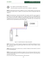
These terminals are internally connected to the negative side of the power supply (24 V
dc). Because the power supply negative side is normally connected to an earth (shield) point,
these terminal can be also be considered a ground terminals. Signal cable screens should be
connected to the earth only at one of the ends of the screened cable. Leave unconnected if the
vibration screen is connected to the earth in another place.
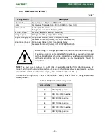
Figure 6 -
Typical external power supply wiring diagram.
NOTE 4
: These inputs are used for temperature measurement using RTD type temperature sensors
(by 2- and 3-wire method). Only RTD's type PT100 can be used. In 2-wire method, connect
terminal "B" with "b
.”
NOTE 5
: These outputs have a common minus (-) terminal. Therefore, the terminals 35, 37, 39 and
41 are connected together.
NOTE 6
: The power supply for an additional cooling fan is the unit main power (Terminals 1 and 2).
A thermal switch placed inside of the unit supplies the external fan when the inside temperature
increases more than 60ºC.
The unit cover must be removed to have access to these terminals.
Summary of Contents for CX300
Page 1: ......
Page 2: ......
Page 4: ...Doc 2016002 CX300 MODULE User manual 3 ...
Page 6: ...Doc 2016002 CX300 MODULE User manual 5 ...


