


Doc.2016002
CX300 MODULE – User manual
-21-
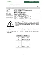
8.
SOFTWARE CONFIGURATION
Each unit can be configured to meet the demands of customer application.
Software configuration will be done with an external PC application:
CX300Config
.
For more details, please read the
CX300Config User Manual
.
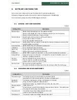
8.1.
GENERAL UNIT CONFIGURATION
Table 4
Configuration
Description
Module Type
[READ-ONLY] Module type can be CX200 or CX300
Module code CX300 has a local LCD display, placed onto the front panel.
Module coded CX200
doesn’t
have a display.
Module Name
Module name can be any text with max.17 letters.
Longer names will be truncated.
This is the 'friendly' module name.
Board Version
[READ-ONLY] This is a number to identify the module firmware version and the
specific hardware installed.
Serial Number
[READ-ONLY] This is the Module Serial Number
IP Address
This is the Module TCP/ IP Address
Max. Freq.
Range
This can be set to 3200 Hz or to 6400 Hz.
Will be the same for all vibration channels
Resolution
[READ ONLY] - Spectrum resolution - is the same for all vibration channels!
Relay settings
Relay can be set to be 'Fail-safe' - energized if is no alarm condition exists, or
'Normal' - energized on alarm
Start-up
multiplier
Alarms multiplier factor during start-up
Only for vibration and BE measurements.
Can be set from a list (X 1.5 up to X 10.0)
Start-up time
Start-up time [1 to 255 seconds]
The alarm multiplier is acting only in this time interval, after the starting-up.
8.2.
VIBRATION AND BE MEASUREMENTS
Table 5
Configuration
Description
Transducer type
Transducer type to be connected (or set to NOT USED)
Selected from a list: Accelerometer, Velocity or Displacement
Sensitivity
Transducer sensitivity in 'mV/g', 'mV/mm/sec' or 'mV/um'
Show Unit
Show unit for this vibration measurement
Selection of: mm/s
2
, g, mm/sec, m/sec, in/sec, μm, mm, inch
Show Detection
RMS, Peak or P-P
Scale
Scale (in Show units) for this vibration measurement channel - This will be also
the scale for mA Output, if is
enabled.
Transducer LO
Transducer lower bias voltage allowed. Min -24V
Used to check transducer integrity
Transducer HI
Transducer higher bias voltage allowed. Max.+24V
Summary of Contents for CX300
Page 1: ......
Page 2: ......
Page 4: ...Doc 2016002 CX300 MODULE User manual 3 ...
Page 6: ...Doc 2016002 CX300 MODULE User manual 5 ...


