background image

Doc.2016002


CX300 MODULE – User manual 


-25- 

11.


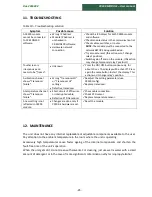
TROUBLESHOOTING 

Table 10 

 Troubleshooting solution 

Symptom 

Possible cause 

Solution 

A CX300 module 
cannot be connected 
to CX-MON300 
software. 


Wrong IP Address 


Module IP Address is 
unchecked in  
CX-MON300 software 


Hardware network 
connection 


Check the IP Address for both CX300 module 
and software. 


Check module status in the communication list. 


Check cables, switches, or router. 

NOTE:

 The module must be connected to the 

network BEFORE being switched-on. 


Try a module reset (this action won’t change 
relay’s position).


Switch again off and on the module, (this action 

may change temporary relay’s position!) 


Touchscreen is 
irresponsive and 

seems to be “

frozen


Unknown 


Press the ON/ OFF button continuously, for 
about 10 sec. The display will be shut-off. Press 
again the same button to start the display. This 

action won’t change relay’s position.


A vibration channel 

shows “

Transducer 

failure”


Wrong “Transducer LO” 
or “Transducer HI” 

settings  


Defective transducer 


Readjust the setting parameters (use 
CX300Config). 


Replace transducer. 

A temperature channel 

shows “Transducer 
failure”.


Short-circuit of RTD wires 
or interrupted cable; 


Defective RTD transducer 


Check cable connection. 


Check RTD sensor. 


Replace temperature sensor. 

A new setting is not 
reflected in CX300 
module. 


Changes are done only if 
CX300 is hardware reset. 


Reset the module. 


12.


MAINTENANCE 

The unit does not have any internal replaceable or adjustable  components available to the user. 
Pay attention to the ambient temperature in the room where the unit is operating. 

Excessively  high  temperatures  cause  faster  ageing  of  the  internal  components  and  shorten  the 
fault-free time of the unit's operation. 

When the unit gets dirt, do not clean with solvents. For cleaning, just use warm water with a small 
amount of detergent or in the case of more significant contamination ethyl or isopropyl alcohol. 


Summary of Contents for CX300

Page 1: ......

Page 2: ......

Page 3: ...CX300 MODULE User manual Doc 2016002 2 E mail mainttech live se www mainttech se CX300 MODULE User manual Document revision REV D DOC 2016002 June 2017 ...

Page 4: ...Doc 2016002 CX300 MODULE User manual 3 ...

Page 5: ...l denotes especially important guidelines concerning the installation and operation of the device Not complying with the guidelines denoted by this symbol may cause an accident damage or equipment destruction This symbol denotes especially important characteristics of the unit Read any information regarding this symbol carefully IF THE DEVICE IS NOT USED ACCORDING TO THE MANUAL THE USER IS RESPONS...

Page 6: ...Doc 2016002 CX300 MODULE User manual 5 ...

Page 7: ...e 13 6 DEVICE INSTALLATION 14 6 1 UNPACKING 15 6 2 ASSEMBLY 16 6 3 CONNECTION TERMINALS 17 7 HARDWARE CONFIGURATION 20 7 1 ACCELEROMETER POWER 20 7 2 VOLTAGE FOR SPEED SENSOR 20 8 SOFTWARE CONFIGURATION 21 8 1 GENERAL UNIT CONFIGURATION 21 8 2 VIBRATION AND BE MEASUREMENTS 21 8 3 TEMPERATURE MEASUREMENTS 22 8 4 SPEED MEASUREMENT 23 9 NORMAL STARTING SEQUENCE 24 10 CX300 LED INDICATOR 24 11 TROUBLE...

Page 8: ...Doc 2016002 CX300 MODULE User manual 7 ...

Page 9: ... attempt to disassemble repair or modify the unit yourself The unit has no user serviceable parts Defective units must be disconnected and submitted for repairs at an authorized service center In order to minimize fire or electric shock hazard the unit must be protected against atmospheric precipitation and excessive humidity Do not use the unit in areas threatened with excessive shocks vibrations...

Page 10: ... Four vibration input channels suitable for ICP Accelerometers velocity and displacement sensors High frequency range and resolution suitable for wide variation type of machines Fast acquisition time high sampling rate 4 to 20 mA output for all vibration channels Four temperature input channels for PT100 RTD 2 or 3 wires One speed measurement channel Bearing fault estimator BE Two galvanic isolate...

Page 11: ...required A D resolution 16 bits Spectrum resolution Selectable 0 5 1 or 2 Hz Total value HPF Selectable none 5 or 10 Hz Total value LPF Selectable from 200 to 6400 Hz Accelerometers supply 4 mA 24 V dc Bearing estimator Bearing Energy Coefficient BE BE HPF 500 Hz Temperature inputs 4 X PT100 2 or 3 wires Channels 4 Temperature range Selectable Min 50ºC Max 300 ºC Speed input 1 Speed range 1 Hz to ...

Page 12: ...mation Technology Equipment EN 60950 RoHS directive 2002 95 EC Flammability Rating Complies with UL 508 UV resistance Complies with UL 508 Case style DIN Rail Case material Polycarbonate Case dimensions mm 213 x 185 x 120 Display Optional 3 5 graphic TFT 16 bit color 320 x 240 pixels touchscreen navigation EMC PN EN 61326 1 Safety requirements According to PN EN 61010 1 Installation category II Po...

Page 13: ...work independently If the unit is equipped with a local display the measurement result and alarms status are available on the screen The unit still can be connected via Ethernet to a computer running CX MON300 application Figure 1 Stand alone typically application CX300 Module with touchscreen display CX200 Module without display 200 with 4 RTD 4 4 20 mA outputs and 4 relays 300 with 4 RTD 4 4 20 ...

Page 14: ...ning CX MON300Client application Figure 2 Network typically application 5 3 CX MON300 Monitoring Software There are two free software applications delivered with any CX300 unit CX MON300 CX MON300Client CX MON300 Software is able to manage the measurements from up to 10 CX300 units The software is similar with a SCADA system and can be configured by the user Scheduled On Alarm or On demand the mea...

Page 15: ...afety and resistance to interference occurring in a typical industrial environment In order to take full advantage of these characteristics installation of the unit must be conducted correctly and according to the local regulations Read the basic safety requirements prior to starting the installation Ensure that the power supply voltage corresponds to the nominal voltage 18 to 36 V DC ALL INSTALLA...

Page 16: ... from the protective packaging check for transportation damage Figure 4 CX300 enclosure dimensions in mm Any transportation damage must be immediately reported to the carrier Also write down the unit serial number located on the housing and report the damage to the manufacturer ...

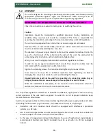
Page 17: ...cuit the connection cables must be terminated with the appropriate insulated cable tips Tighten the clamping screws The recommended tightening torque is 0 5 Nm Loose screws can cause fire or defective operation Over tightening can lead to damaging the connections inside the units and breaking the thread Unused terminals must not be used for connecting any connecting cables e g as bridges because t...

Page 18: ... Connections of power supply voltage and measurement signals are executed using the screw connections of the unit s enclosure 6 3 CONNECTION TERMINALS Each terminal is labeled with a number The actual meaning of each terminal is labeled inside on the terminals cover Figure 5 Connection terminals The table below shows the standard terminal assignment of the CX300 unit Table 2 Terminal assignment Te...

Page 19: ...negative See Note 5 40 OUT4 mA positive 41 OUT4 mA negative See Note 5 42 RL1 CC Relay contact 43 RL1 NC Relay contact 44 RL1 NO Relay contact 45 RL2 CC Relay contact 46 RL2 NC Relay contact 47 RL2 NO Relay contact 48 RL3 CC Relay contact 49 RL3 NC Relay contact 50 RL3 NO Relay contact 51 RL4 CC Relay contact 52 RL4 NC Relay contact 53 RL4 NO Relay contact 54 LCD power supply Not accessible for th...

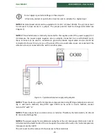
Page 20: ...le screens should be connected to the earth only at one of the ends of the screened cable Leave unconnected if the vibration screen is connected to the earth in another place Figure 6 Typical external power supply wiring diagram NOTE 4 These inputs are used for temperature measurement using RTD type temperature sensors by 2 and 3 wire method Only RTD s type PT100 can be used In 2 wire method conne...

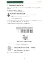
Page 21: ... these need a constant current power supply of 4 mA 24Vdc A mini switch with four positions is placed on the baseboard Change the position of the switches according to the next table Table 3 Switch No ON position OFF position 1 Supply enabled Supply disabled 2 Supply enabled Supply disabled 3 Supply enabled Supply disabled 4 Supply enabled Supply disabled Figure 7 Power to accelerometers switches ...

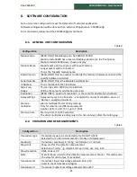
Page 22: ...channels Resolution READ ONLY Spectrum resolution is the same for all vibration channels Relay settings Relay can be set to be Fail safe energized if is no alarm condition exists or Normal energized on alarm Start up multiplier Alarms multiplier factor during start up Only for vibration and BE measurements Can be set from a list X 1 5 up to X 10 0 Start up time Start up time 1 to 255 seconds The a...

Page 23: ...10 seconds Map Warning Vib Map vibration Warning Alarm to a specific Relay Selected from a list none RLY1 RLY2 RLY3 or RLY4 Map Danger Vib Map vibration Danger Alarm to a specific Relay Selected from a list none RLY1 RLY2 RLY3 or RLY4 Map Warning BE Map BE Warning Alarm to a specific Relay Selected from a list none RLY1 RLY2 RLY3 or RLY4 Map Danger BE Map BE Danger Alarm to a specific Relay Select...

Page 24: ... make sure that the machine is not running The manufacturer is not responsible for any damages caused by improper settings Modification should be conducted by qualified personnel During setting modification all the available safety requirements should be considered NOTE The four current outputs 4 to 20 mA are available only for Total Vibration value By request additional four current outputs can b...

Page 25: ...FF for a period of 2 seconds Check the network integrity and RESET the module 10 CX300 LED INDICATOR Green LED ON Indicate that the main processor running OK OFF Indicate a 5V power supply failure or the main processor is defective Red LED OFF This is the normal status after the starting sequence ON Vibration cannot be acquired defective A D converters or a fault onto the Vibration Board BLINK A m...

Page 26: ...action won t change relay s position A vibration channel shows Transducer failure Wrong Transducer LO or Transducer HI settings Defective transducer Readjust the setting parameters use CX300Config Replace transducer A temperature channel shows Transducer failure Short circuit of RTD wires or interrupted cable Defective RTD transducer Check cable connection Check RTD sensor Replace temperature sens...

Page 27: ... for private networks 10 0 0 0 10 255 255 255 172 16 0 0 172 31 255 255 192 168 0 0 192 168 255 255 We will refer to the first block as 24 bit block the second as 20 bit block and the third as 16 bit block Note that the first block is nothing but a single class A network number while the second block is a set of 16 continuous class B network numbers and the third block is a set of 255 continuous c...

Page 28: ...st comments be specific and include the product name and version We cannot provide personal responses to every message received but please be assured that all feedback will be given careful consideration for future improvements to the MaintTech documentation or software Technical Support Contact Details For any problem regarding this application feel free to contact our support team at mobind mobi...

Reviews: