Mainship 40 Trawler Single & Twin • DC Electric Systems
7.4
of yellow (negative) wires attached. All electrical circuits
require a ground, so all grounds are joined in sections at
“grounding blocks”.
You will notice on the right hand side of the grounding
block pictured a green wire attached, this is part of the
“Bonding System”.
The purpose of the bonding system is to protect your
boat’s underwater components from electrolysis or gal-
vanic corrosion. Examples of underwater components
would be the propellers, propeller shafts, rudders, or
engine / generator and seawater intake valves.
Electrolysis and galvanic corrosion occurs primarily in
salt water but can occur to a lesser degree in fresh water.
Salt water allows electric current to flow from anodic to
cathodic material. Any two metals from two components
and their relative position in the galvanic rating table
will determine which metal loses material (anode) and
which metal remains largely undisturbed (cathode). The
distance apart in the galvanic table of the two metals
determines the rate of wear.
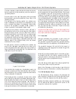
To help prevent corrosion, sacrificial zinc anodes are
wired to the underwater components of your boat, such
as the propeller shafts and rudders, then connected to a
large sacrificial zinc anode plate (fig. 7.5) attached to the
underwater area of the transom.
Figure 7.5 Zinc Plate
The sacrificial zinc anodes are considerably easier and
cheaper to replace and their deterioration will not affect
the performance of your boat as would the deterioration
of any underwater components.
The bonding system is a network of wires (color coded
green) that are connected to all metallic underwater com-
ponents within the interior of the hull, which makes them
one unit for electrical current purposes. This network of
wires is then attached to the sacrificial zinc anode locat-
ed on the transom, which allows corrosion of the anode
but prevents corrosion of the underwater components.
General maintenance of the bonding system consists of
yearly replacement of the sacrificial anodes. This should
be completed during the spring launch procedure for
example. The anode may require more frequent replace-
ment, depending on your docking location and the length
of your boating season. If possible, check the anode for
excessive corrosion midway through your boating sea-
son. If excessive corrosion is noted, have your dealer or
a competent technician replace the sacrificial zinc anode.
Periodically check the wiring connections to make sure
they are tight and free of corrosion. Tighten and clean
connections as necessary.
Important: DO NOT PAINT any part of the sacrificial zinc
anode as it will retard the flow of electric current through
them and render them ineffective.
7.1.7 Generator
Although technically the generator is part of the AC
System, because it supplies AC power. The starting of
the generator requires DC power, the generator starting
receives power from the batteries in the lazarette area.
The generator supplies 120 volt 60 hz AC power for
operating devices and equipment controlled through the
AC Distrbution Panel.
When the generator indicating light is on and the genera-
tor breakers are ON, AC power is supplied to both the
generator and AC control panel devices and equipment.
The ON light at the AC Distribution Panel is
illuminated.
The slide bar prevents power from being supplied from
shore power when using the generator.
Refer to the “Operation and Procedures” part of the AC
Electric section for information on starting the generator.
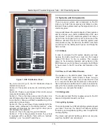
7.1.8 DC Distribution Panel
The DC Distribution Panel, located in the starboard aft
side of the salon controls DC current throughout the boat.
Figure 7.8 lists the breakers and circuits they protect.
Besides the battery selector switches you must engage
the DC Main at the MDP to provide DC power to the
respective components or systems.
Summary of Contents for 40 Trawler Single
Page 8: ...Mainship 40 Trawler Single Twin Operator s Manual H This Page Intentionally Left Blank ...
Page 14: ...Notes Mainship 40 Trawler Single Twin Introduction 1 6 ...
Page 18: ...2 4 Mainship 40 Trawler Single Twin Documents and Forms Fig 2 1 ...
Page 23: ...2 9 Mainship 40 Trawler Single Twin Documents and Forms Notes ...
Page 24: ...2 10 Mainship 40 Trawler Single Twin Documents and Forms This Page Intentionally Left Blank ...
Page 33: ...3 9 Mainship 40 Trawler Single Twin Warranty SAMPLE ...
Page 35: ...3 11 Mainship 40 Trawler Single Twin Warranty SAMPLE ...
Page 36: ...Notes 3 12 Mainship 40 Trawler SIngle Twin Warranty ...
Page 37: ...V1 011508 P N 1034082 40 Trawler Single Twin Single Twin Boating Safety Safety Chapter 4 ...
Page 54: ...Mainship 40 Trawler Single Twin Boating Safety 4 18 Notes ...
Page 66: ...Notes Mainship 40 Trawler Single Twin Fuel System 5 12 ...
Page 76: ...Notes Mainship 40 Trawler Single Twin Underwater Gear 6 10 ...
Page 92: ...Mainship 40 Trawler Single Twin DC Electric Systems 7 16 Notes ...
Page 102: ...Mainship 40 Trawler Single Twin AC Electric Systems 8 10 This Page Intentionally Left Blank ...
Page 110: ...Mainship 40 Trawler Single Twin Water Systems 9 8 Notes ...
Page 146: ...Mainship 40 Trawler Single Twin Maintenance 13 14 This Page Intentionally Left Blank ...
Page 151: ......
Page 152: ......
Page 153: ......
Page 154: ......
Page 155: ......
Page 156: ......
Page 157: ......
Page 158: ......
Page 159: ......
Page 160: ......
Page 161: ......
Page 162: ......
Page 163: ......
Page 164: ......
Page 165: ......
Page 166: ......
Page 167: ......
Page 168: ......
Page 169: ......
Page 170: ......


