background image

 © 2015 Sensata Technologies

Installation

20

ME-RC50/ME-ARC50 

– Full feature remotes with backlit LCD 

display and LED indicators for inverter and charger status. Provide 

full menu access for easy selection and adjustment; come with a 

50’ cable. The ME-RC50 and ME-ARC50 are used for many inverter 

models and have additional features that are not functional with the 

MMSA1012 inverter/charger.

Do I need an optional ME-RC or ME-ARC remote?

An optional ME-RC50 or ME-ARC remote control provides additional 

settings not provided by the DIP switch settings. Review the 

following information and the adjustable settings in the remote 

owner’s manual to determine if the inverter’s (DIP switch) default 

settings (per Table 4-3) are adequate for your system needs.

Search Watts:

 This setting allows you to enable the power-saving 

Search mode circuitry and to adjust the power level at which the 

inverter will “wake up” and start inverting. This function is adjusted 

to 5W (“wakes up” and inverts if loads exceed 5 watts) on the MMSA 

inverter/charger.

LBCO: 

This setting determines when the inverter turns off based on 

low battery voltage (inverter turns off automatically once battery 

voltage remains below this setting for 

more than 

one minute). This 

protects the batteries from over-discharge and the AC loads from 

unregulated power (brown-outs).

Battery AmpHrs: 

This setting allows the user to input the battery 

bank size in amp hours (AHs), which provides information to the 

charger on how long to charge the batteries in the Absorb charging 

stage.

Battery Type: 

Sets the type of batteries being used in the system 

which provides information to the charger to determine what voltage 

level to charge the batteries.

Charge Rate: 

This setting uses a percentage of the charger’s 

maximum output to determine the output charge rate. This setting 

can be used to limit the amount of current that the charger can use 

(leaving more current available to power loads); or, to ensure small 

battery banks are not overheated because of a charge rate that is 

too high.

VAC Dropout: 

Sets the minimum AC voltage that can be present 

on the AC input before the unit transfers from Standby mode to 

Invert mode. This protects the AC loads from utility outages and 

brown-outs.

Summary of Contents for MMSA Series

Page 1: ...Owner s Manual MMSA1012 Pure Sine Wave Inverter Charger ...

Page 2: ...allation operation use or maintenance Due to continuous improvements and product updates the images shown in this manual may not exactly match the unit purchased Restrictions on Use The MMSA1012 inverter charger may only be used in life support devices and systems with the express written approval of Sensata Technologies Failure of this inverter can reasonably be expected to cause failure of that ...

Page 3: ... installing or using this product All electrical work must be performed in accordance with local state and federal electrical codes This product is designed for indoor compartment installation DO NOT expose to rain snow moisture or liquids of any type Use insulated tools to reduce the chance of electrical shock or accidental short circuits Remove all jewelry such as rings watches bracelets etc whe...

Page 4: ... reduce the chance of explosion always connect the cables to the batteries first Then connect the cables to the inverter Use insulated tools at all times Always verify proper polarity and voltage before connecting the batteries to the inverter To reduce the chance of fire or explosion do not short circuit the batteries In the event of accidental exposure to battery acid wash thoroughly with soap a...

Page 5: ...3 0 Setup 24 3 1 Adjusting DIP Switch Settings 24 4 0 Operation 30 4 1 MMSA Top Panel Features 30 4 2 Operating Modes 34 4 3 Protection Circuitry Operation 37 4 4 Battery Temperature Sensor Operation 39 4 5 Summary of Inverter DIP Switch Settings 40 5 0 Maintenance Troubleshooting 41 5 1 Recommended Inverter Battery Care 41 5 2 Troubleshooting 41 5 3 Performing an Inverter Reset 44 5 4 Performing ...

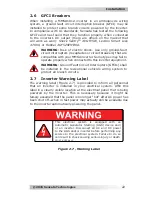
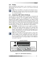
Page 6: ...ory Connections 21 Figure 2 7 Warning Label 22 Figure 3 1 DIP Switch Summary 24 Figure 4 1 Top Panel Power Switch and LED Indicators 30 Figure 4 2 Charge Status Indicators 31 Figure 4 3 Automatic 4 Stage Charging Graph 36 Figure 4 4 BTS Temperature to Voltage Change 39 Figure 5 1 Resetting the Inverter 44 Figure B 1 Series Battery Wiring 47 Figure B 2 Parallel Battery Wiring 48 Figure B 3 Series P...

Page 7: ...udes isolated input output neutrals and a 15 battery temperature sensor Figure 1 1 MMSA1012 Inverter 1 2 How an Inverter Charger Works An inverter takes direct current DC from your batteries and turns it into alternating current AC like you use at home The MMSA1012 inverter charger also takes alternating current and transforms it into direct current to recharge your batteries There are three modes...

Page 8: ... of batteries installed in your application as well as the battery s capacity and age Other factors such as the battery s state of charge and temperature can also affect the length of time your appliances can run Depending on your inverter capacity larger electrical appliances can be used for short durations However loads that are used for longer periods such as stoves or water heaters can quickly...

Page 9: ...ssory and remote ports easily accepts several optional remote controls and the Battery Temp Sensor 1 5 1 External MMSA1012 Features This section covers the many features available on the MMSA1012 inverter 1 Power ON OFF Switch LED Status Indicators a momentary pushbutton switch that alternately turns the inverter on or off and five LED status indicators INV BULK ABSORB FLOAT and FAULT for monitori...

Page 10: ...ut Connection a strain relief clamp with a 3 ft standard plug in power cord to provide AC power to the inverter 8 DC Ground Terminal a ground connection used to tie the exposed chassis of the inverter to earth ground or to the vehicle s DC grounding system Terminal accepts CU AL conductors from 14 to 6 AWG 2 1 mm2 to 13 3 mm2 ...

Page 11: ...ckage DIP Switch 10 individual slide switches that are used to determine the MMSA inverter charger s operating parameters 12 3 Port Terminal Block three spring loaded clip terminals to connect an optional 20 amp DC auxillary device a ignition control switch and a ground remote control switch 13 Exhaust Vent ventilation openings that allow heated air to be removed by the internal cooling fan 14 Mod...

Page 12: ... end with an Anderson connector SB175 attached Figure 1 7 17 Negative DC Terminal the inverter s connection to the negative terminal on the battery bank The MMSA1012 comes with one end of a black 2 AWG DC cable already connected to the inverter s negative terminal Figure 1 6 and the other end with an Anderson connector SB175 attached Figure 1 7 18 Intake Vent ventilation openings to pull in air to...

Page 13: ... temperature for better charging performance and longer battery life If the temperature sensor is not installed and the batteries are subjected to large temperature changes the battery life may be shortened The BTS cable comes with a RJ11 connector that plugs into the BTS port on the side of the inverter Figure 1 4 Item 9 Refer to Figure 2 4 for installation instructions and to Section 4 4 for inf...

Page 14: ...ou in planning and designing your installation 2 1 1 Unpacking and Inspection Carefully remove the MMSA1012 inverter from its shipping container and inspect all contents Verify the following items are included MMSA1012 inverter charger Connected positive and negative battery cables with Anderson connector attached Battery Temperature Sensor MMSA1012 Owner s Manual Warning label If items appear to ...

Page 15: ...ensata Technologies Installation 9 Figure 2 1 MMSA1012 Model Basic Installation Diagram Overcurrent Device AC Loads AC OUT AC IN Battery Bank Medical devices DC Disconnect DC Ground Anderson Connectors Monitor ...

Page 16: ... not covered under warranty Cool The inverter is rated for indoor use only and should be protected from direct exposure to the sun or to any equipment that produces extreme heat The ambient air temperature should be between 4 F and 140 F 20 C to 60 C realize that the inverter s continuous output power and continuous charger current are rated at 113 F 45 C so the cooler the better within this range...

Page 17: ...rientation To meet regulatory requirements the MMSA1012 inverter charger can only be mounted on a horizontal surface right side up or up side down on a shelf table or vertical surface right side up on a wall bulkhead as shown in Figure 2 2 The inverter must be mounted on a non combustible surface and this surface and the mounting hardware must be capable of supporting at least twice the weight of ...

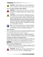
Page 18: ...the inverter and the battery bank WARNING Even though DC voltage can be regarded as low voltage significant hazards may be present particularly from short circuits of the battery system CAUTION The inverter is NOT reverse polarity protected which means if the negative and positive battery voltage is connected to the inverter backwards the inverter will likely be damaged Use a voltmeter to verify t...

Page 19: ...ditional voltage drops and these extra connection points may loosen during use A brief spark or arc may occur when connecting the battery cables to the inverter DC terminals this is normal and due to the inverter s internal capacitors being charged Before routing the wiring color code the DC cables wires to the battery bank with colored tape or heat shrink tubing RED for positive WHITE for negativ...

Page 20: ...rd size overcurrent device may be used if the de rated cable ampacity falls between the standard overcurrent devices found in the NEC If the distance from the inverter to the battery is 5 feet 1 5 m the DC wire will need to be increased Longer cable distances affect the performance of the inverter See the lower part of Table 2 1 to determine the minimum DC wire size needed for various distances gr...

Page 21: ...ounded wiring system The idea is to connect the metallic chassis of the various enclosures together to have them at the same voltage potential to reduce the possibility for electric shock For most installations the inverter chassis and the negative battery conductor are connected to the system s ground bond via a safety grounding conductor bare wire or green insulated wire at only one point in the...

Page 22: ...ect DC voltage and polarity have been verified Info For optimum performance a minimum battery bank of 200 AH is recommended Depending upon the type of batteries you use in the installation 6 or 12 VDC the batteries must be wired in series parallel or series parallel to provide 12 VDC see Appendix B Battery Information for guidance on wiring batteries together The interconnecting DC wires must be s...

Page 23: ...laced in the positive RED DC cable line between the inverter s positive DC terminal and the battery s positive terminal RED as close to the battery as possible DC Ground Wire Route an appropriately sized DC grounding wire GREEN or bare wire from the inverter s DC Ground Terminal Figure 1 3 Item 8 to a dedicated system ground Torque to 45 in lbs 2 3 6 1 Wiring the Battery Bank to a MMSA1012 Inverte...

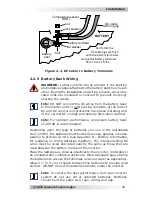
Page 24: ... the inverter 7 Connect the other end of the BTS to the negative terminal of the last battery string place hardware per Figure 2 4 Final Checks Connect the two Anderson connectors Ensure the DC wire connections on the battery terminals fuse lugs DC circuit breaker and disconnect are flush on the surface of the DC terminals and the hardware lock washer and nut used to hold these connections in plac...

Page 25: ...s ON OFF switch and the remote s ON OFF button if connected Refer to the Switch 3 section on page 26 for information on setting up a ground control switch for your system and for other conditions and considerations that affect this feature 2 5 Remotes and Connections 2 5 1 Remotes and Remote Settings Sensata Technologies offers several remotes that let you monitor the inverter charger and enable y...

Page 26: ...A inverter charger LBCO This setting determines when the inverter turns off based on low battery voltage inverter turns off automatically once battery voltage remains below this setting for more than one minute This protects the batteries from over discharge and the AC loads from unregulated power brown outs Battery AmpHrs This setting allows the user to input the battery bank size in amp hours AH...

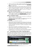
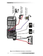
Page 27: ...ation 21 ON OFF Ignition Control Switch ICS BTS INVERT AC IN FAULT ON OFF MM R MM C Ground Control Switch GCS AUX OUT AUX Ex Service lamp BULK ABSORB FLOAT Battery Bank B B B B B Monitor Remote Figure 2 6 MMSA1012 Accessory Connections ...

Page 28: ...standards Sensata has tested the following GFCI s and has found that they function properly when connected to the inverter s AC output there are others on the market that will work as well Shock SentryTM VGF15W Leviton Smart Lock 7899 or Hubbel GF520EMBKA WARNING Risk of electric shock Use only ground fault circuit interrupters receptacles or circuit breakers that are compatible with your MMSA inv...

Page 29: ...ing indicating the inverter is providing AC power If the LED is blinking turn off Search mode DIP Switch 4 in UP position 5 Check the output voltage of the inverter by connecting a multimeter to the outlets powered by the inverter Verify the voltage is 120 VAC 5 VAC 6 Turn on or connect a load and verify it comes on Continue to keep the load connected and turned on 7 Press the remote s ON OFF swit...

Page 30: ... parameters This section shows how to set the DIP switch and provides information on each switch setting s function Use the DIP switch adjustments described below to configure your MMSA1012 inverter charger CAUTION The MMSA does not warn against or disallow incorrect DIP switch settings Ensure the settings used to charge the batteries the Absorption Done Time and Battery Type selections are carefu...

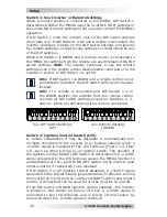
Page 31: ...orced off and cannot be turned on when the 12VDC signal is removed Switch 1 Use Inverter or Remote Settings When a remote control is connected to the MMSA DIP Switch 1 determines whether the MMSA uses the inverter s DIP settings or the connected remote s settings to set up and or control the MMSA s operation If DIP Switch 1 is UP the inverter runs on the DIP switch settings See Table 4 3 If DIP Sw...

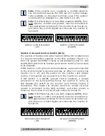
Page 32: ...ses the MMSA inverter to automatically come on and the ON OFF switch on the inverter and remote control if connected to be disabled If DIP Switch 3 is UP ground control disabled a ground connection to the GCS terminal is ignored and has no effect on turning the inverter on or off and the switch on the inverter and remote control if connected can be used to turn the inverter on and off If DIP Switc...

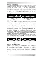
Page 33: ...fer to the label on the back side of the inverter or Table 6 1 to determine the inverter s 100 or maximum charge rate With DIP Switch 5 set UP 100 Charge Rate the charger can deliver 100 of the available charging capability of the inverter With DIP Switch 5 set DOWN 30 Charge Rate the charge rate will be limited to 30 of the maximum charging capability of the inverter This 30 setting is provided t...

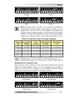
Page 34: ...nn Deka Discover and Trojan AGM batteries Info Voltages shown in Table 3 1 are based on the Battery Temperature Sensor BTS being disconnected or at a temperature of 77 F 25 C If the BTS is connected the charge voltage changes based on the temperature around the BTS to ensure the batteries receive the correct charge voltage even if they become cold or hot see Section 1 5 2 GEL AGM 2 Switches 8 9 Ab...

Page 35: ...UP use inverter settings When DIP Switch 1 is UP and an EQ charge is started the charger uses the inverter s battery type selection to determine the EQ voltage and time period To EQ charge ensure the charger is in the Float Charge or Full Charge stage and then set DIP Switch 10 to DOWN The EQ charge begins if Battery Type selection allows see Table 3 1 and continues for 2 hours and then automatica...

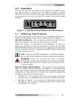
Page 36: ...ust be pressed to start the unit Once the inverter has been turned on pressing the ON OFF switch alternately turns the unit off and on Info The power ON OFF pushbutton is a small momentary type switch which operates by lightly pressing and releasing WARNING When any external AC power is passing through the inverter and is present on the output pressing the ON OFF switch will not remove this AC pow...

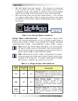
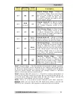
Page 37: ... ON OFF OFF Bulk Charge Stage Charger is delivering maximum current to the batteries Charger remains in bulk charge until the absorb target voltage1 is achieved Blink x1 sec 3 OFF OFF Charger Back off in Bulk Charge mode Charger is in Charger Back off2 limiting charging current to the battery Charge Status LED Indicators The at a glance charge LED s Figure 4 2 provide information on the inverter s...

Page 38: ...er goes to Full Charge mode If battery voltage drops to a low level 12 7 VDC the charger automatically initiates another float charge 1st ON 2nd ON 3rd ON Equalize Charge Stage Charger is in the Equalize Charge stage regulating the current to maintain the battery at the equalize target voltage1 Note Each charge status LED indicator comes on quickly in sequence Note1 Target Voltage The temperature ...

Page 39: ... the inverter has turned off because the connected loads are larger than the inverter s output capacity or there is a short on the output wiring Restart the inverter once the AC loads are reduced or the wiring short has been removed To restart the inverter momentarily press the ON OFF button on the inverter or remote Blinks x5 then off for 2 secs Internal Fault the inverter has turned off because ...

Page 40: ... the inverter is turned on it operates either by Searching or Inverting depending on the connected AC loads Searching When the inverter is first turned on the automatic Search feature is disabled This feature is provided to conserve battery power when AC power is not required In this mode the inverter pulses the AC output looking for an AC load i e electrical appliance Whenever an AC load greater ...

Page 41: ...ging capability than most chargers available today When an AC power source is connected to the MMSA the inverter monitors the AC input for acceptable voltage Once the inverter has accepted the AC input the AC transfer relay will close and charging will begin Once charging the DC voltage is monitored to determine the charging stage If the DC voltage is low 12 9 VDC the charger begins bulk charging ...

Page 42: ...rs after four hours in the float charging The Full charge stage maintains the batteries without overcharging preventing excessive loss of water in flooded batteries or drying out of GEL AGM batteries In this stage the charger is turned off and begins monitoring the battery voltage If the battery voltage drops low 12 7 VDC the charger will automatically initiate another four hours in float charge D...

Page 43: ...tor can handle causing the generator s output voltage to constantly fall below the inverter s input VAC dropout threshold Info You must use the ME MR ME RC or ME ARC remote to adjust the VAC dropout setting which in turn determines the VAC dropout threshold Info When switching from Inverter mode to Standby mode the inverter waits approximately 15 seconds to ensure the AC source is stable before tr...

Page 44: ...r will shut down To start operating after this fault the inverter would need to be restarted turned back on after the inverter s AC loads are reduced removed Over temperature If internal power components begin to exceed their safe operating temperature level the inverter will shut down to protect itself from damage The inverter s status LED turns OFF to indicate the over temperature fault conditio...

Page 45: ...ple the nominal absorb charge voltage for a flooded battery at 77 F 25 C is 14 6 VDC If the battery temperature is 95 F 35 C the absorb charge voltage would decrease to 14 3 VDC 14 6 VDC 0 3 change If the temperature sensor is NOT installed the charge voltages are not compensated and the battery maintains the charge it had at a temperature of 77 F 25 C Without a BTS the life of the batteries may b...

Page 46: ...M2 and GEL Absorb Time2 DIP Switches 8 9 Both UP1 60 Minutes Other DIP settings 90 120 150 minutes EQ Enable2 DIP Switch 10 UP1 EQ Charge Disabled DOWN Start EQ Charge LowBatCutOut2 10 0 VDC1 VAC Dropout2 80 VAC1 Note1 Inverter and DIP switch default settings Note2 Optional ME RC and ME ARC remote controls provide additional settings for these functions Table 4 3 MMSA Inverter DIP Switch Settings ...

Page 47: ...g cables Check fill battery water levels Liquid Lead Acid batteries only Check individual battery voltages for those that vary more than 0 3 VDC from each other equalize if possible or replace Check all cable runs for signs of chafing replace if necessary Check the inverter s cooling vents clean as necessary 5 1 1 Off Season Storage If placing a vehicle into seasonal storage it is recommended that...

Page 48: ...rging source alternator solar panels or other external charging sources is used to charge the battery bank Reduce or turn off any other charger to the inverter batteries to allow the voltage level to drop Over temperature condition status indicator blinks on 3 times every 3 secs Internal temperature of the inverter has risen above acceptable limits loads too great for inverter to continuously oper...

Page 49: ...t setting 80 VAC default Check incoming AC voltage to inverter s input ensure it is present and above the VAC Dropout setting Appliances turn off and on or there is low AC output power Loose AC output connections Tighten AC output connections Loose corroded battery cables Clean and tighten all cables Low batteries Recharge or replace batteries Inverter AC output voltage too low or too high using A...

Page 50: ...es the inverter s internal capacitors are being charged 5 3 Performing an Inverter Reset To perform an inverter reset also known as a soft reset 1 Remove all AC power i e shorepower to the inverter 2 Press and hold the inverter s ON OFF pushbutton for approximately 10 seconds or until all LEDs come on in sequence from the first INV to the last FAULT 3 Release the ON OFF pushbutton once all LEDs tu...

Page 51: ...iciency maximum 84 Power factor 0 95 Input current rated output 7 AAC Temperature compensation Yes with BTS General Features and Capabilities Protection circuitry Low High Battery Over temp Overload Corrosion protection PCB s conformal coated powder coated chassis AC Output GFCI outlet AC Input 3 ft cord Output circuit breaker 15A Input circuit breaker 20 AAC Internal cooling Yes 0 to 59 cfm varia...

Page 52: ...o automatically start your generator based on low battery condition or high temperature It works with 12 24 and 48 volt battery banks and includes a 4 position DIP Dual In line Package switch which provides the ability to change the relay timing configurations to allow compatibility with most generators Battery Monitor Kit The ME BMK Battery Monitor Kit is a single battery bank amp hour meter that...

Page 53: ...ies best suited for the inverter installation and cost Use only the same battery type for all batteries in the bank For best performance all batteries should be from the same lot and date This information is usually printed on a label located on the battery B 3 Battery Configuration The battery bank must be wired to match the inverter s DC input voltage specifications 12 VDC In addition the batter...

Page 54: ...igure B 3 four 6 VDC 200 AH batteries are combined into two strings resulting in a 12 VDC 400 AH battery bank Figure B 2 Parallel Battery Wiring 12 volt battery bank total capacity 400 AH overcurrent protection 12 volts 100 AH 12 volts 100 AH 12 volts 100 AH 12 volts 100 AH To 12 VDC Inverter Parallel Wiring Wiring the batteries in parallel increases the total run time the batteries can operate th...

Page 55: ...urrent protection Series String 6 VDC 6 VDC 12 volt battery bank 2 strings of two 6 volt batteries wired in series connected in parallel overcurrent protection Parallel String 200 AH 200 AH 12 volt battery bank parallel two 12 volt batteries to 12 VDC inverter total capacity 200 AH Parallel String 100 AH 100 AH overcurrent protection 12 volts 100 AH overcurrent protection 6 volts 200 AH 6 volts 20...

Page 56: ...ermined by the price paid by the original purchaser Sensata shall not be liable for any other losses or damages 4 Upon request from Sensata Technologies the original purchaser must prove the product s original date of purchase by a dated bill of sale itemized receipt 5 The original purchaser shall return the product prepaid to Sensata in Everett WA or to one of Sensata s Authorized Service Centers...

Page 57: ...rning your product directly to Sensata for repair you must 1 Return the unit in the original or equivalent shipping container 2 Receive a Return Materials Authorization RMA number from the factory prior to the return of the product to Sensata for repair 3 Place RMA numbers clearly on the shipping container or on the packing slip When sending your product for service please ensure it is properly pa...

Page 58: ...num Dimensions Products Manufactured by Sensata Technologies 2211 West Casino Rd Everett WA 98204 Phone 425 353 8833 Fax 425 353 8390 Web www Magnum Dimensions com MMSA1012 Owner s Manual PN 64 0073 Rev A ...

Reviews: