


© 2015 Sensata Technologies
Installation
18
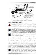
2. Connect a short wire (same rating as the DC wires) from one
end of the fuse block to the positive terminal of the
fi
rst battery
string (see Figure B-3).
3. Connect another short wire (same rating as the DC wires) from
the other end of the fuse block to one end of the DC disconnect.
4. Using a compatible Anderson connector (not supplied), route
and connect its appropriately sized DC positive wire (RED) to
the other end of the DC disconnect.
Battery Bank’s DC Negative Wire
5. Route and connect the appropriately sized DC negative wire
(BLACK) from the Anderson connector you supplied (Step 4)
to the negative terminal of the last battery string. This ensures
even charging and discharging across the entire battery bank.
Battery Temperature Sensor
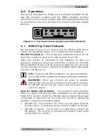
6. Connect the RJ11 connector end of the BTS to the BTS port
(Figure 1-4, Item 9) on the inverter.
7. Connect the other end of the BTS to the negative terminal of the
last battery string (place hardware per Figure 2-4).
Final Checks
• Connect the two Anderson connectors.
• Ensure the DC wire connections (on the battery terminals, fuse
lugs/DC circuit breaker, and disconnect) are
fl
ush on the surface
of the DC terminals, and the hardware (lock washer and nut)
used to hold these connections in place are stacked correctly
(see Figure 2-4).
• Verify all DC connections are torqued from 10 to 12 ft-lbs.
• Once the DC connections are completely wired and tested, coat
the terminals with an approved anti-oxidizing spray.
• If batteries are in an enclosure, check the hold down brackets
and all connections. Close and secure the battery enclosure.
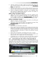
2.4 Connecting to the 3-Port Terminal Block
The MMSA inverter/charger provides a 3-port terminal block on the
right side of the unit (Figure 2-5) that can be used to connect an
auxiliary DC load—(AUX), an ignition control switch—(ICS), and a
ground control switch—(GCS). See also Figure 2-6.
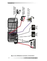
Figure 2-5, MMSA1012’s 3-Port Terminal Block