


© 2015 Sensata Technologies
Installation
12
Mounting holes x4
[¼” (.64 cm) diameter]
10.0"
(25.4 cm)
16¾"
(42.5 cm)
6¾" (17.1 cm)
8½" (21.6 cm)
7½" (19.1 cm)
6¾" (17.1 cm)
R ESE T
RE
SE
T
TE STTE
ST
AU
X
O
U
T
AC
I
N
AC
O
U
T
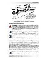
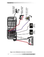
Figure 2-3, MMSA1012 Inverter Dimensions
2.3 DC
Wiring
This section describes the inverter’s required DC wire sizes, the
recommended disconnect/overcurrent protection, and how to make
the DC connections to the inverter and the battery bank.
WARNING:
Even though DC voltage can be regarded as “low
voltage”, signi
fi
cant hazards may be present, particularly
from short circuits of the battery system.
CAUTION:
The inverter is NOT reverse polarity protected—
which means if the negative and positive battery voltage is
connected to the inverter backwards, the inverter will likely
be damaged. Use a voltmeter to verify the correct polarity
BEFORE connecting the DC wires.
CAUTION:
DO NOT connect the battery cables to the
inverter until all wiring is complete and the correct DC
voltage and polarity have been veri
fi
ed.