


© 2015 Sensata Technologies
Installation
11
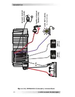
Close to the battery bank
–
As with any inverter, it should be
located as close to the batteries as possible. Long DC wires tend to
lose ef
fi
ciency and reduce the overall performance of an inverter.
However, the unit should not be installed in the same compartment
as the batteries or mounted where it will be exposed to gases
produced by the batteries. These gases are corrosive and will
damage the inverter; also, if these gases are not ventilated and
allowed to collect, they could ignite and cause an explosion.
Accessible
–
Do not block access to the inverter’s remote control
and accessory ports. Also, allow enough room to access the DC
wiring connections as they will need to be checked and tightened
periodically. See
Figure 2-3 for the MMSA’s dimensions.
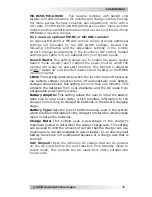
Mounting Orientation
– To meet regulatory requirements, the
MMSA1012 inverter/charger can only be mounted
on a horizontal
surface (right-side up or up-side down on a shelf/table) or vertical
surface (right-side up on a wall/bulkhead), as shown in Figure 2-2.
The inverter must be mounted on a “non-combustible” surface,
and this surface and the mounting hardware must be capable of
supporting at least twice the weight of the inverter. After determining
your mounting position, use the base of the inverter’s chassis as
a template to mark your mounting screw locations. Remove the
inverter and drill pilot holes into the mounting surface.
As this unit is used in a mobile application, you may want to place
fl
exible washers or bushings between the mounting surface and the
inverter’s mounting
fl
anges to reduce vibration.
Once the inverter has been properly mounted, you can begin to wire
the DC connections.
Figure 2-2, Approved Mounting Orientations
Shelf Mounted
(right-side up)
Shelf Mounted
(up-side down)
Wall Mounted
(right-side up)