Magnetrol Jupiter JM4 Safety Manual Download Page 14

14


ORI-652 Jupiter

®

 Model JM4 Magnetostrictive Transmitter – SIL Safety Manual
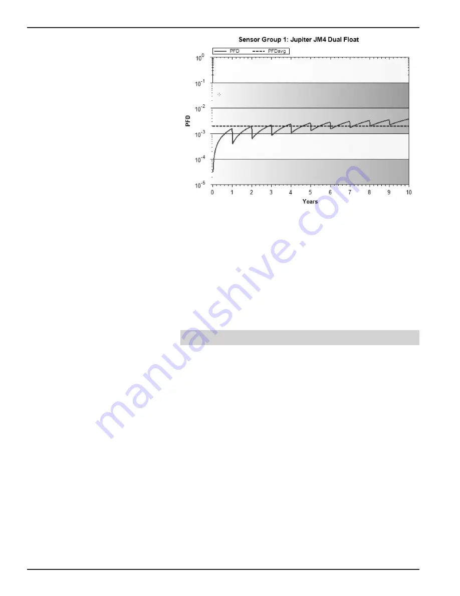
PFD

AVG

 value for a single Model JM4-511x-xxx (two floats) 

with proof test intervals of one year.

It is the responsibility of the Safety Instrumented Function designer to 

perform calculations for the entire SIF.
For SIL 2 applications, the PFD

AVG

 value needs to be 

 10

-3

 and 

<

 10

-2

This means that for a SIL 2 application, the PFD

AVG

 for a 1-year Proof 

Test Interval of the Model JM4-511x-xxx is approximately equal to 

20% of the range.
These results must be considered in combination with PFD

AVG

 values 

of other devices of a Safety Instrumented Function (SIF) in order to 

determine suitability for a specific Safety Integrity Level (SIL).

7.5 

Report: Lifetime of Critical Components

According to section 7.4.9.5 of IEC 61508-2, a useful lifetime, 

based on experience, should be assumed.
Although a constant failure rate is assumed by probabilistic 

estimation method, this only applies provided that the useful 

lifetime of components is not exceeded. Beyond their useful 

lifetime the result of the probabilistic calculation method is 

therefore meaningless, as the probability of failure significantly 

increases with time. The useful lifetime is highly dependent on 

the subsystem itself and its operating conditions.
The assumption of a constant failure rate is based on the bathtub 

curve. Therefore it is obvious that the PFD

AVG

 calculation is only 

valid for components that have this constant domain and that 

the validity of the calculation is limited to the useful lifetime of 

each component.
The expected useful life of JUPITER Model JM4-511x-xxx is at 

least 50 years.

Summary of Contents for Jupiter JM4

Page 1: ...oftware v1 x Magnetostrictive Level Transmitter This manual complements and is intended to be used with the Orion Instruments Jupiter Model JM4 Magnetostrictive Level Transmitter Installation and Oper...

Page 2: ...lation 6 5 3 Skill Level of Personnel 6 5 4 Necessary Tools 6 5 5 Configuration 6 5 5 1 General 6 5 5 2 Configuration 7 5 5 3 Write Protecting Locking 7 5 6 Site Acceptance Testing 7 5 7 Recording Res...

Page 3: ...section of the wire alloy This in turn creates a vibratory disturbance which begins to travel through the wire at a very constant rate of speed The disturbance is later detected via a sensing device...

Page 4: ...operly under the low alarm condition The only unsafe mode is when the unit is reading an incorrect level within the 4 20 mA range 2 deviation MAGNETROL defines a safe failure as one in which the 4 20...

Page 5: ...e Description Files is also required if HART is used Manufacturer Code 56 hex Model JM4 Device ID 56DF hex device revision 1 DD revision 1 For device installations in a classified area the relevant sa...

Page 6: ...NOTE This SIL evaluation has assumed that the customer will be able to acknowledge an over or undercurrent condition via the Logic Solver 5 3 Skill Level of Personnel Personnel following the procedure...

Page 7: ...9 999 NOTE Default Password 0 Password disabled Refer to the Model JM4 Installation and Operating Manual Bulletin ORI 650 for additional information on password pro tection It is required that after c...

Page 8: ...o maintain the appropriate Safety Integrity Level of a Safety Instrumented System it is imperative that the entire system be tested at regular time intervals shown as TI in the appropriate standards T...

Page 9: ...esent Status Present Status should be OK b Review the EVENT HISTORY i Messages in the EVENT HISTORY must be investigated and understood ii Corrective actions should be taken for critical messages that...

Page 10: ...have evidence of excessive noise iv If possible compare to Echo curve from commissioning to assure that performance has not changed significantly c Choose the menu DIAGNOSTICS ADVANCED DIAGNOSTICS IN...

Page 11: ...e manufacturer that the level transmitter Magnetostrictive 4 20 mA Model JM4 511x xxx is suitable for the use in safety instrumented systems according to IEC 61511 1 if the safety instructions and fol...

Page 12: ...12 ORI 652 Jupiter Model JM4 Magnetostrictive Transmitter SIL Safety Manual...

Page 13: ...IL 2 HFT 0 Single Float SFF 93 1 PFDavg 1 97E 03 Dual Float SFF 91 9 PFDavg 1 96E 03 Proof Test Interval Annually refer to PFD Graph below 7 4 PFD Graph The resulting PVDAVG Graph generated from the e...

Page 14: ...Lifetime of Critical Components According to section 7 4 9 5 of IEC 61508 2 a useful lifetime based on experience should be assumed Although a constant failure rate is assumed by probabilistic estima...

Page 15: ...Safety Related Systems ANSI ISA 84 00 01 2004 Part 1 IEC 61511 1Mod Func tional Safety Safety Instrumented Systems for the Process Indus try Sector Part 1 Hardware and Software Requirements ANSI ISA 8...

Page 16: ...ry inspection finds the cause of the claim to be covered under the warranty If the trouble is the result of conditions beyond our control or is NOT covered by the warranty there will be charges for la...

Reviews: