


IMPULSE®•G+/VG+ Series 4 24 V Power Supply Installation Manual - November 2011
1-29
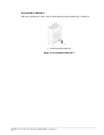
Connection Diagram
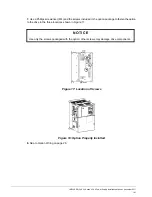
Figure 31 illustrates the 24 VDC Power Supply Option and drive connections.
Figure 31: Connection Diagram for Drive and Option
NOTE:
24 VDC external power supply input is supplied by the customer.
Wire Gauges and Tightening Torques
Table 4: Wire Gauges and Tightening Torques
Terminal
Number
Screw
Size
Tightening
Torque
N-m (in-lb)
Bare Cable
Crimp Terminals
Wire
Type
Applicable
Gauges mm
2
Recomm.
Gauges mm
2
Applicable
Gauges mm
2
Recomm.
Gauges mm
2
24, 0, FE
M2
0.22 to 0.2
(1.95 to 2.21)
Standard wire:
0.25 to 1.0
(24 to 17 AWG)
Single line:
0.25 to 1.5
(24 to 16 AWG)
0.75
(18 AWG)
0.25 to 0.5
(24 to 20 AWG)
0.5
(20 AWG)
Shielded
cable, etc.
WA R N I N G
Fire Hazard
Tighten terminal screws to the specified tightening torque. Loose electrical connections could
result in death or serious injury by fire due to overheating. Tightening screws beyond the
specified tightening torque may cause erroneous operation, damage the terminal block, or
cause a fire.
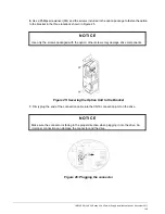
N O T I C E
Heat shrink tubing or electrical tape may be required to ensure that cable shielding does not
contact other wiring. Insufficient insulation may cause a short circuit and damage the option or
drive.


