MAINTENANCE
lr/,@
T [I 2 runes
' I. /9
' '“°“
<¤ 2 _ i i~
• I
· "r :
...» . · ’ Hi/mm 1 ~
| ’ II .
» :·=·
{B E · l V ey a>’°:T; —..
', . I ¤ ` caf" '•¤ "
03 " .1 I »' ·. 0 O
{ 4; Q" ,
E QN 2 rb °
REF
I ·\___ 1
I
391-851
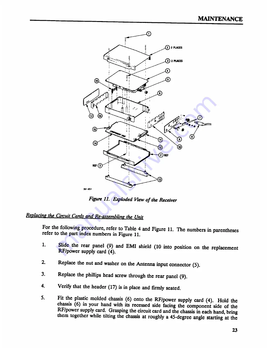
Figure 11. Exploded View of the Receiver
Reglacing the Circuit Cards and Re-assembling the Unit
For the following procedure, refer to Table 4 and Figure 11. The numbers in parentheses
refer to the part index numbers in Figure 11.
1. Slide the rear panel (9) and EMI shield (10 into position on the replacement
RF/power supply card (4).
2. Replace the nut and washer on the Antenna input connector (5).
3. Replace the phillips head screw throu the rear anel 9).
P
4. Verify that the header (17) is in place and tirmly seated.
5. Fit the plastic molded chassis (6) onto the RF/power supply card (4). Hold the
chassis (6) in your hand with its recessed side facing the component side of the
RF/power supply card. Grasping the circuit card and the chassis in each hand, bring
them together while tilting the chassis at roughly a 45-degree angle starting at the
23


