SYSTEM INSTALLATION
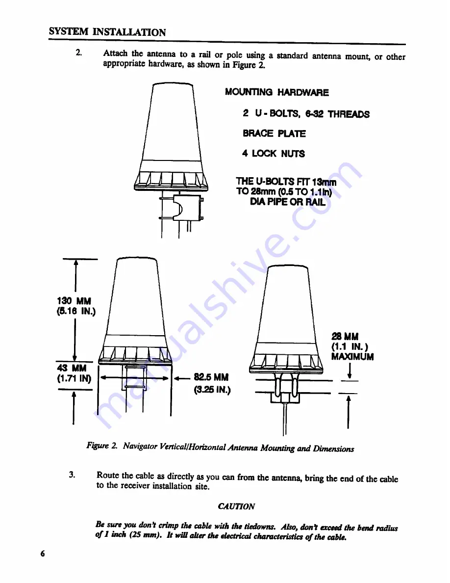
2. Attach the antenna to a rail or pole using a standard antenna mount, or other
appropriate hardware, as shown in Figure 2.
MOUNTING HARDWARE
2 U - BOLTS. 6-32 THREADS
BRACE PLATE
4 LOCK NUTS
THE U-BOLTS FIT 13mm
TO 28mm (0.5 TO 1.1In)
DIA PIPE OR RAIL
130 MM
(5.16 IN.)
28 MM
(1.1 IN.)
MAXIMUM
as uu l
(1.71 IN) <— 82.5 MM . 1
T (3.25 IN.) T
Figure 2. Navigator Vertical/Horizontal Antenna Mounting and Dimensions
3. Route the cable as directly as you can from the antenna, bring the end of the cable
to the receiver installation site.
CAUTYON
Be sure you don? crimp the cable with the tiedowns. Also, don'! exceed the bend radius
of I inch (25 mm). It will alter the electrical characteristics ofthe cable.
6


