OPERATING & MAINTENANCE INSTRUCTION MANUAL
MODELS 427A (R-1), 428A (R-2), AND 429A (R-3) WELD HEADS
REV. AB
MODEL 514 TUBEMASTER OR 515/516 PIPEMASTER POWER SUPPLY
31
THESE DOCUMENTS, AND THE CONTAINED INFORMATION HEREIN, ARE PROPRIETARY AND ARE NOT TO BE REPRODUCED, USED OR DISCLOSED TO
OTHERS FOR MANUFACTURE OR FOR ANY OTHER PURPOSE, EXCEPT AS SPECIFICALLY AUTHORIZED, IN WRITING, BY MAGNATECH, LLC
EXAMPLE:
Set-up for 1.5" O.D. tube (38mm O.D.). Install spring engagement post in Hole A on inner
pivoting arms (closest to Weld Head I.D.). Install the pivoting arm in Hole A (closest to O.D. of Weld Head
in rotary plate).
NOTE:
If the pivoting arm is located in the proper hole, the tungsten should be perpendicular to the
workpiece. This is based upon the following criteria:
Use of Magnatech Short Gas Cup P/N 7312.
Tungsten stick out of 1/8" (3mm) beyond gas cup.
Gap of approximately 1/16" (1.6mm) from tungsten tip to pipe O.D.
For positive arc ignition and a stable arc, the smallest diameter tungsten electrode suitable for the weld
current range should be used. Use either 2% Thoriated or Ceriated tungsten. Ceriated tungsten offers
improved starting and usable life.
The tungsten tip-to-work distance or arc length when kept to a minimum will produce a more stable arc and
deeper penetration. For general tube welding, the arc gap should be adjusted between 0.75mm (.03") and
1.3mm (.05").
Install a tungsten electrode in the torch. Select the proper collet and collet body for the size tungsten to be
used.
The tungsten must protrude beyond the edge of the gas cup sufficient for the wall thickness of the pipe or
tube to be welded. Once the proper stick-out has been determined, using a simple gauge or scale to
measure stick-out each time the tungsten is replaced will eliminate the need for wire aim adjustments, if filler
wire is being used.
Insert the tungsten through the collet and collet body and screw the collet body into the torch by hand.
Tighten the tungsten by rotating the torch back cap.
Be certain that the ceramic cup is in snug contact with the silicone rubber coating of the torch.
A gas cup clip is provided with each Redhead model. This spring clip slips around the gas cup and a short
cable connects it to the body of the Weld Head (ground). Use of this clip significantly aids positive arc
ignition.
CAUTION:
Do not over tighten the gas cup into the body of the torch; only light contact is required for a gas-
tight seal. Over tightening may damage the rubber surface of the torch.
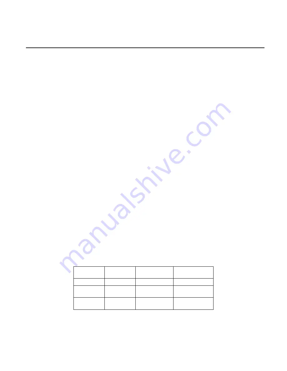
Table 7 - Pivot Arm Pipe O.D.
Arm
Location
Post
Location
Tube Size
Pipe Size
A
A
1.5”(38mm)
1” (33mm)
B
B
1.0” (25mm)
½” (21mm and
¾” (27mm)
C
C
0.5” (13mm)
¼” (14mm and
3
/
8
” (17mm)
9.6
R-2 and R-3 Lead/Lag Adjustment
The electrode angle can be adjusted relative to the pivot arm by loosening the two torch mounting screws,
rotating the torch, and then retightening the screws.
There are no alternate pivot post locations required on the R-2 and R-3.


