


OPERATING & MAINTENANCE INSTRUCTION MANUAL
MODELS 427A (R-1), 428A (R-2), AND 429A (R-3) WELD HEADS
REV. AB
MODEL 514 TUBEMASTER OR 515/516 PIPEMASTER POWER SUPPLY
28
THESE DOCUMENTS, AND THE CONTAINED INFORMATION HEREIN, ARE PROPRIETARY AND ARE NOT TO BE REPRODUCED, USED OR DISCLOSED TO
OTHERS FOR MANUFACTURE OR FOR ANY OTHER PURPOSE, EXCEPT AS SPECIFICALLY AUTHORIZED, IN WRITING, BY MAGNATECH, LLC
1.
The Head is clamped on the Pipe by means of a 3-point contact, which is accomplished using a sliding
"V" block on one side, and an adjusting clamping bar which contacts the pipe surface directly opposite
the "V" block. Adjust the sliding "V" plate to the appropriate pipe O.D. (mm) size. This is done by
loosening the two (2) screws in the "V" plate and lining up the "notch" in the bottom of the sliding "V"
plate with scale. (The scale is calibrated in mm pipe OD size.) With the sliding "V" plate in the correct
position, tighten the two screws securely.
2.
The clamping bar must now be adjusted for the pipe size to be welded. Move the clamp lever (with the
red plastic handle) to the "clamped" position (which extends the clamping bar towards the pipe surface).
Rotate the knurled adjusting knob until the clamping bar is "pointing" at the center of the "V" plate (a
straight edge placed along the axis of the clamping bar should intersect the "V" plate directly at its
center.
Loosen the screw that retains the clamping bar in the clamping anvil. Rotate the clamp lever to the
unclamped position. Insert the Weld Head over the pipe surface. Rotate the clamping knob to the
"clamped" position. Hold the Weld Head in position on the pipe. Push the clamping bar into contact
with the surface of the pipe and tighten in this position with the one (1) screw provided.
CAUTION: I
t may be necessary to back off on the arc gap control spring adjustment prior to performing
Step 2 if the Weld Head is being used on a larger pipe than for which it was previously set. Failure to do
this will cause excessive spring load of the torch arc gap control mechanism, making it difficult to firmly hold
the Weld Head on the pipe surface.
3.
The clamping mechanism is now approximately adjusted for the pipe size. The clamping bar has been
adjusted so that it just contacts the pipe surface and retains the pipe at a 3-point contact with the "V"
plate. To obtain rigid clamping, move the clamp lever to the unclamped position. Rotate the knurled
adjuster nut approximately 1/2 turn and move the clamp lever to the clamped position. In the clamped
position the Weld Head should be rigidly mounted on the pipe with sufficient force to prevent accidental
rotation of the Head during welding. Some final adjustment of the clamp force may be required by
repeating Step 3.
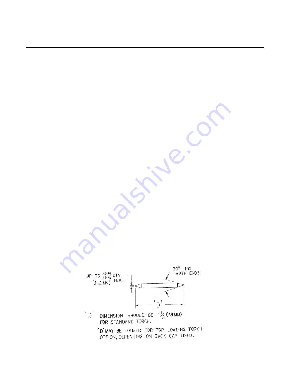
9.4
Install Tungsten Electrode and Adjust Arc Gap
The diameter, tip geometry and arc gap are important factors for precision repetitive welding. Consult
Tungsten Electrode and Adjust Arc Gap
and
Recommended Tungsten Electrode Tip
Geometry
for the proper diameter and tip geometry.
Figure 2 - Tungsten Electrode and Adjust Arc Gap


