Magnadyne PL50 Installation Manual Download Page 19

19

User Discretion Silent Arming: 

Your security system can be instructed to become armed or disarmed without the horn/siren chirps by

the remote transmitter. To operate this feature at any time, simply press the Arm/Disarm and #2 Button

for regular transmitter or the Lock and Unlock buttons for code-hopping transmitters at the same time.

The combination of the two signals will instruct the security system to arm or disarm silently. 
Note: For 3 button transmitters button #3 can be programmed to operate the silent arming feature. (See

Remote Feature Programming for more information) (Applies to PL60 Only)

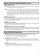
Ignition Controlled Door Locking: 

(Door lock activation must be installed)

When switched on in “DIP Switch Programming”, ignition controlled locking is active 3 seconds after the

ignition key is set the on position, the door locks will automatically become locked. When the ignition key

is turned to the off position, the door locks will unlock.

Note: If a protected entrance (Door) is open when the ignition key is set to the on position, the door locks

will not lock. This is a non-deletable protective measure.

Channel #2 Output:

Press and hold the channel #2 activation button for 3 seconds. The designated channel 2 output wire

from the alarm become grounded for as long as button #2 is pressed.

Dual Zone Sensor with Pre-Warning Indicator: 

(If Installed)

1. Close all protected entrances and place the alarm in an armed condition.

2. Rap the vehicles body panels to activate the pre-warning zone of any dual zone type sensor.

3. When the pre-warning indicator is triggered, the horn/siren will beep 1 time.

Step 11: Speciality Feature and Optional Equipment Testing

Power Requirements . . . . . . . . . . . . . . . . . . . . . . . . 12.5 Volts Negative Ground

Trigger Inputs . . . . . . . . . . . . . . . . . . . . . . . . . . . . . . Grounded Pin Switch, Positive Pin Switch, 

Electronic Sensor Ground, 0.6 Volt Current Drop

Current Requirements . . . . . . . . . . . . . . . . . . . . . . . Less Than 15mA Armed or Disarmed

Timers  . . . . . . . . . . . . . . . . . . . . . . . . . . . . . . . . . . . . Programmable Automatic Arming Timer

Programmable Re-Arming Timer

60 Second RF Tamper Re-Arming Timer

5 Second Zone By-Pass Re-Activation Timer

Grounded Output Wire Capacity (White Wire) . . 500mA

Siren Output Wire Capacity . . . . . . . . . . . . . . . . . . 2  amps

Channel 2 Pulsed Output. . . . . . . . . . . . . . . . . . . . 300mA

By-Pass Zones . . . . . . . . . . . . . . . . . . . . . . . . . . . . . 2  Zones

Transmitter Frequency . . . . . . . . . . . . . . . . . . . . . . 302mHz

Regular TX Code Combinations . . . . . . . . . . . . . . . 500,000 Available 

Code Hopping TX Code Combinations . . . . . . . . . . 1  Trillion Available 

Code Method . . . . . . . . . . . . . . . . . . . . . . . . . . . . . . Digital Trinary

Receiver Channels . . . . . . . . . . . . . . . . . . . . . . . . . No  More  Than 3

Specifications

Summary of Contents for PL50

Page 1: ...t 1997 Magnadyne Corporation For Technical Assistance 800 638 3600 For Fax on Demand Technical Assistance 800 994 9977 Must be a Registered Dealer to Use Fax on Demand System INSTALLATION MANUAL Remot...

Page 2: ...ith the alarm kit is one pin switch and one mounting bracket To install the switch either in the truck or under the hood find a suitable location where the switch will make contact with the hood or tr...

Page 3: ...equiring positive voltage or more than 300mA to trigger the horn relay will require an additional relay to increase current capabilities Blue Wire with White Stripe Channel 3 Output Applies to PL60 On...

Page 4: ...hting dimmer switch Damage to the dimmer will result use a volt meter to test the connection point before connecting the red white wire While checking rotate the dimmer switch to make sure you do not...

Page 5: ...Wire Main Ground Input Connect the black wire directly to the frame of the vehicle Use a bolt and nut to secure the wire Scrape away any grease or paint that might prevent a good connection Yellow Wi...

Page 6: ...Brown Wire Unlock Green Wire Lock Blue Wire Unlock Violet Wire 3 Pin Black Plug ALA DL1 Relay Pack Power Door Lock Unlock Activation 3 Wire Positive Trigger Door Lock System Lock Out 12 Volts Input U...

Page 7: ...ne wire to lock and unlock the doors Example When the door lock controller sees a signal thru a resistor it will unlock If a signal is received without a resistor the doors will lock Some use 2 resist...

Page 8: ...r Ground To 12V or Ground Driver s Door Rear Door Passenger Door Switch Door Lock Relay Control Module Lock Unlock 12V Must Add ALA984H Relay Drivers Door Switch Cut Unlock Remaining Doors Unlock Driv...

Page 9: ...ection of this manual Page 17 ACC START OFF ON Cut Starter 2 Pin Plug from Control Module Unlock Driver s Door First Wiring for 5 Wire Ground at Rest Door Locking Systems 87 87A 85 86 30 87 87A 85 86...

Page 10: ...th White Stripe Output from Alarm Flashing Lights White Orange Wire Optional Dome Light Illumination and Lighted Pathway Illumination Output to Domelight or Input to Relay or White Purple Wire Orange...

Page 11: ...Using Optional 30 Amp Relay Applies to PL50 Only 87 86 85 30 Orange Wire SPST ALA984H Relay Not Supplied Output to Dome Light or To Constant 12 Volts Input to Relay or Insert Orange Wire into the Fir...

Page 12: ...e Valet Override Switch is in the Off Position S t e p 1 Switch in Off Position Switch in On Position Valet Override Switch Switch the Valet Switch On then Off 1 Time The horn siren will stop sounding...

Page 13: ...2 Regular Arm Dis 2 S t e p 6 To Code 2 Button Push the Valet Switch 2 Times Represent 1 Time On Off The LED will be solid red and the horn siren will chirp 1 time S t e p 7 2x Push the 2 Button The...

Page 14: ...rming Automatic Arming of Alarm Off 3 Silent Arming from 3 Button Transmitter s Aux Button Off 4 Safety Illumination Sentinel System Off R Disarm the Security System The LED will be off and the horn s...

Page 15: ...seconds after door is closed and rearm 60 seconds after remote disarm 4 Beeps Automatic Arming On Alarm will arm 70 seconds after door is closed and rearm 60 seconds after remote disarm 5 Beeps Automa...

Page 16: ...nner regardless of the alarm model Test each feature by following the procedures enclosed to insure proper operation Remote Panic 1 Press and hold the arm disarm for regular transmitters or panic butt...

Page 17: ...e security system is in the valet mode Note If the unit is in valet mode the LED will be on solid when the ignition key is on only When the ignition key is off the LED will flash once every 5 seconds...

Page 18: ...with the transmitter the locks will become locked 2 Disarm the alarm with the transmitter the locks will become unlocked RF Tamper Re Arm Note This feature is activated automatically when the alarm i...

Page 19: ...on deletable protective measure Channel 2 Output Press and hold the channel 2 activation button for 3 seconds The designated channel 2 output wire from the alarm become grounded for as long as button...

Page 20: ...View of Housing Dip Switches Black Wire Antenna Do Not Ground Power Door Lock Harness Socket Black Valet Override Socket Blue 1 2 3 ON Black Wire Ground to Vehicle Frame Yellow Wire To Ignition Switc...

Reviews: