Magnadyne PL50 Installation Manual Download Page 16

16

To test the basic functions of the alarm system (all models) repeat the following procedures.

1. Turn off the ignition key and exit the vehicle closing all protected entrances.

2. Press the arm/disarm or lock button on the transmitter. You will hear a horn/siren chirp, the parking

lights will flash one time and the LED status indicator will flash at normal speed.

3. Wait 5 seconds, then open a protected entrance. The horn/siren will begin to sound. Press the arm/disarm

or unlock button once again and the horn/siren will stop sounding. (No Disarm Chirp Indicator)

Note: If you disarm the alarm when the horn/siren is sounding, there are no disarming chirps. When you

disarm the alarm when the siren is off, there will be disarming chirps.

4. Follow procedures 2 and 3 for all other protected entrances.

Step 10: General Testing

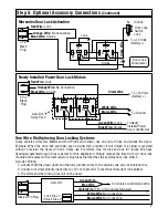
About Multiple Car Programming:

Note 1: Regular transmitters with 2 buttons can operate 2 alarm systems. (Alarm models do not have to

be the same)
Note 2: Code Hopping transmitters will only operate 1 alarm system.
To perform multi-car programming, all transmitters must first be marked car to indicate which car/alarm

they are for. ie car #1, car #2 etc. Once this is done, follow the specific programming procedure for each

model alarm you are programming and program the arm/disarm button and CH#2 buttons according

which car they will operate.

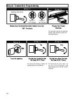
Step 9: Multiple Car Programming

Each specialty feature listed operates in the same manner regardless of the alarm model. Test each feature

by following the procedures enclosed to insure proper operation.

Remote Panic:

1. Press and hold the arm/disarm (for regular transmitters) or panic button (for code hopping transmitter)

down for approximately 3 seconds.

2. The alarm will begin to sound and the parking lights will begin to flash.

3. Press the arm/disarm or panic button once again and the horn/siren will stop sounding and the lights

will stop flashing.

Note: The remote panic feature has an automatic shut off circuit. When the horn/siren has sounded for

60 seconds, the panic circuit will turn itself off automatically.

Last Door Automatic Arming: 

(If Programmed On) 

Note: The automatic arming feature will not operate unless the alarm input triggers have been connected

directly to the existing or newly installed door jamb pins. Current sensing alone will not activate the

automatic arming circuit.

1. Disarm the alarm.

2. Set the ignition key to the on position, then turn it off.

3. Exit the vehicle. The horn/siren will chirp 1 time when the door is closed.

4. The LED will begin to flash fast.

5. After 10, 20 or 30 seconds have passed (depending on remote feature programming), you will hear a

single chirp. The alarm is now armed.

6. The LED will flash at a regular rate indicating an armed condition.

Note: When the automatic arming feature is activated, so is the RF tamper re-arm circuit. Every time the

alarm is disarmed by remote, the RF tamper re-arm circuit will count for sixty seconds (LED will be

flashing fast) and the alarm will re-arm itself if no one has entered the vehicle. 

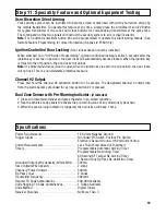
Step 11: Speciality Feature and Optional Equipment Testing

Summary of Contents for PL50

Page 1: ...t 1997 Magnadyne Corporation For Technical Assistance 800 638 3600 For Fax on Demand Technical Assistance 800 994 9977 Must be a Registered Dealer to Use Fax on Demand System INSTALLATION MANUAL Remot...

Page 2: ...ith the alarm kit is one pin switch and one mounting bracket To install the switch either in the truck or under the hood find a suitable location where the switch will make contact with the hood or tr...

Page 3: ...equiring positive voltage or more than 300mA to trigger the horn relay will require an additional relay to increase current capabilities Blue Wire with White Stripe Channel 3 Output Applies to PL60 On...

Page 4: ...hting dimmer switch Damage to the dimmer will result use a volt meter to test the connection point before connecting the red white wire While checking rotate the dimmer switch to make sure you do not...

Page 5: ...Wire Main Ground Input Connect the black wire directly to the frame of the vehicle Use a bolt and nut to secure the wire Scrape away any grease or paint that might prevent a good connection Yellow Wi...

Page 6: ...Brown Wire Unlock Green Wire Lock Blue Wire Unlock Violet Wire 3 Pin Black Plug ALA DL1 Relay Pack Power Door Lock Unlock Activation 3 Wire Positive Trigger Door Lock System Lock Out 12 Volts Input U...

Page 7: ...ne wire to lock and unlock the doors Example When the door lock controller sees a signal thru a resistor it will unlock If a signal is received without a resistor the doors will lock Some use 2 resist...

Page 8: ...r Ground To 12V or Ground Driver s Door Rear Door Passenger Door Switch Door Lock Relay Control Module Lock Unlock 12V Must Add ALA984H Relay Drivers Door Switch Cut Unlock Remaining Doors Unlock Driv...

Page 9: ...ection of this manual Page 17 ACC START OFF ON Cut Starter 2 Pin Plug from Control Module Unlock Driver s Door First Wiring for 5 Wire Ground at Rest Door Locking Systems 87 87A 85 86 30 87 87A 85 86...

Page 10: ...th White Stripe Output from Alarm Flashing Lights White Orange Wire Optional Dome Light Illumination and Lighted Pathway Illumination Output to Domelight or Input to Relay or White Purple Wire Orange...

Page 11: ...Using Optional 30 Amp Relay Applies to PL50 Only 87 86 85 30 Orange Wire SPST ALA984H Relay Not Supplied Output to Dome Light or To Constant 12 Volts Input to Relay or Insert Orange Wire into the Fir...

Page 12: ...e Valet Override Switch is in the Off Position S t e p 1 Switch in Off Position Switch in On Position Valet Override Switch Switch the Valet Switch On then Off 1 Time The horn siren will stop sounding...

Page 13: ...2 Regular Arm Dis 2 S t e p 6 To Code 2 Button Push the Valet Switch 2 Times Represent 1 Time On Off The LED will be solid red and the horn siren will chirp 1 time S t e p 7 2x Push the 2 Button The...

Page 14: ...rming Automatic Arming of Alarm Off 3 Silent Arming from 3 Button Transmitter s Aux Button Off 4 Safety Illumination Sentinel System Off R Disarm the Security System The LED will be off and the horn s...

Page 15: ...seconds after door is closed and rearm 60 seconds after remote disarm 4 Beeps Automatic Arming On Alarm will arm 70 seconds after door is closed and rearm 60 seconds after remote disarm 5 Beeps Automa...

Page 16: ...nner regardless of the alarm model Test each feature by following the procedures enclosed to insure proper operation Remote Panic 1 Press and hold the arm disarm for regular transmitters or panic butt...

Page 17: ...e security system is in the valet mode Note If the unit is in valet mode the LED will be on solid when the ignition key is on only When the ignition key is off the LED will flash once every 5 seconds...

Page 18: ...with the transmitter the locks will become locked 2 Disarm the alarm with the transmitter the locks will become unlocked RF Tamper Re Arm Note This feature is activated automatically when the alarm i...

Page 19: ...on deletable protective measure Channel 2 Output Press and hold the channel 2 activation button for 3 seconds The designated channel 2 output wire from the alarm become grounded for as long as button...

Page 20: ...View of Housing Dip Switches Black Wire Antenna Do Not Ground Power Door Lock Harness Socket Black Valet Override Socket Blue 1 2 3 ON Black Wire Ground to Vehicle Frame Yellow Wire To Ignition Switc...

Reviews: