17
4.2
Automatic Load
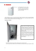
Inside the additional tank there is an engine that handles the pellets at the bottom in order to avoid possible blockages
due to fuel extraction. The engine is powered by the boiler's electronic control unit, connecting the power cables in the
V3 output, corresponding clamps 7 and 8 (see electrical diagram p. 14)
Intake inlet air calibration:
Techincal Parameters
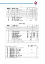
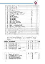
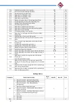
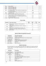
Below are the default technical parameters already prepared in the electronic board.
To make changes to the parameters, access via the Display, select the System Menu and enter the password: 6593.
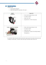
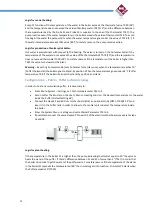
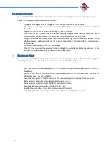
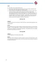
Automatic loading of the plug in which
the supplied hose must be connected,
which in turn must be connected to the
in-outlet, indicated above, present in the
lower part of the boiler.
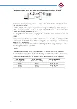
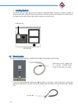
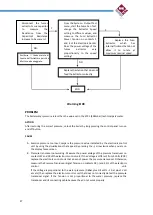
Joining in which the supplied hose should be
connected, which in turn must be grafted into the
inlet socket, indicated above, present in the lower
part of the boiler. By moving the tube shown in the
figure, from right to left and vice versa (↔) it is
possible to increase and reduce the air inflow
during pellet intake.
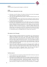
The air during the loading operation is a fluidizer so
in case the pellet should stick along the pipe
connected to the boiler it will be necessary to
increase the air entrance by completely opening
the grey pipe slots in order to increase the air flow
and reduce the flow of pellets so as to avoid
possible blockages.

