background image


11 


Logic for central heating:  

Pump P1 functions if the temperature of the water in the boiler exceeds the thermostat value Th20 (55°) 
and the temperature does not exceed the value of Sanitary water Th20 (70°) and the difference between 
the temperature read by the Probe S1 and Probe S3 is superior to the one of the thermostat Th57). The 
pump is active even if the water temperature in the boiler exceeds the value of thermostat th19. To avoid 
freezing of the water the pumps starts when the water temperature goes under the value of Th18 (5°). If 
the water temperature exceeds th21 value (80°), for safety reasons, the pump remains active. 


Logic for production of Sanitary Hot Water: 
Hot water is predominant with respect to the heating. The valve is turned on the hot water boiler if the 
temperature of the water do not exceed the value of the thermostat ACS Th79 (70°) and the temperature 
does not exceed thermostat Th20 (55°). For safety reasons if the temperature of the boiler is higher than 
Th21 the valve turns towards the plant 

Warning :  By setting Summer mode (only hot water for sanitary use), when the temperature reaches 70° 
(Puffer thermostat) the boilers goes to Stand-by position. When the temperatures goes under 63°C (Puffer 
temperature 79 8°) the boiler interrupts the stand-by position and starts. 

Configuration 4 – P26=4 – Puffer technical storage 

In order to heat an accumulation puffer, it is necessary to:  


Enter  Menu System – Settings, set  Technical parameter P26 to 4  


Set on Puffer Thermostat on the User’s Menu – Heating control – the desired temperature for the water 
inside the Puffer (Default setting 65°)  


Connect the claps 35 and 36 from mother board (IN3)  an optional probe (NTC of 10K @ 25°) and 
insert it in the Puffer tank in order to allow to the central unit to detect the temperature inside 
the boiler  


Enter the System Menu – Settings and set technical Parameter P75 to 9. 


If possible to connect the second pump P2 to exit A2 of the electric motherboard, precisely to claps 
16 and 18. 


Logic for plant heating:    

If the temperature in the boiler S1 is Higher than the pump activating thermostat equal to 50° the system 
heats the water of the puffer  if there’s difference between S1 and S2 of more than 5° (Th57) in order that 
the boiler do not risk to get the water of the puffer warm. For safety reasons if the temperature of the water 
in the boiler (S1) exceeds the temperature of 80° the circulator gets into function. Circulator P2 starts when 
the Puffer exceeds 50° (Th59). 


Summary of Contents for HEVO 14

Page 1: ...TECHNICAL MANUAL HEVO 14 18 21 ENGLISH...

Page 2: ...l bodies During installation the staff must refer to the following Laws and Regulations D M No 37 22 01 2008 Reordering of the provisions on the installation activities of the plants inside the buildi...

Page 3: ...1 5 2 2 Chimney and fumes Pipe 6 2 3 Hydraulic installation 7 Electronic Unit 13 3 1 Schema elettrico 14 3 2 Environment thermostat 15 Loading System 16 4 1 Manual Loading 16 4 2 Automatic Load 17 Tec...

Page 4: ...erage smokes temperature C 154 83 158 83 160 83 Average draft Pa 10 10 10 Inner tank capacity Kg 20 20 20 Autonomy h 7 25 5 25 5 25 Heatable volume nominal m 350 410 490 Air taking 50 50 50 Smokes exi...

Page 5: ...table protection as long as it does not reduce the minimum section to 100 cm2 The minimum ambient volume must not be less than 20 m The air inflow can also be obtained from rooms adjacent to the insta...

Page 6: ...commended to extend the vertical stretch by one meter and for each horizontal section it is recommended to extend the vertical section by 2 meters In the case of vertical developments greater than 7 m...

Page 7: ...e 2 5bar Expansion vase 6 lt Not in the picture Heating Production of Hot Water Wilo circulator high performance 2 5 6 Air Escape automatic Safety valve 2 5bar Expansion vase 6 lt Not in the picture C...

Page 8: ...er easier for any extraordinary maintenance Effect the connection by using intercept valves sphere gate valves in order to simplify any maintenance operation Connect the output of the safety valve to...

Page 9: ...ereafter the function logics will be explained Configuration 0 P26 0 Default from production Apparel coupled with a gas boiler in the heating only version In order to connect the boiler to another gas...

Page 10: ...h21 in order to guarantee a constant production of hot water In this case if the installed boiler produces also hot water the flow the exchanger and the motorized valve are already originally present...

Page 11: ...mostat the boilers goes to Stand by position When the temperatures goes under 63 C Puffer temperature 79 8 the boiler interrupts the stand by position and starts Configuration 4 P26 4 Puffer technical...

Page 12: ...boiler passes into the Stan by state when both probes S2 and S3 are satisfied and therefore both Puffer Probe thermostats Low and high have reached the temperature set in the User s Menu Heating Manag...

Page 13: ...vent from the radiator taps Check that the pressure of the system is stable checking for any water leaks In case the pressure is stable and there is no water leakage the product is hydraulically ready...

Page 14: ...fer DHW Boiler S2 Display MultiTouch G W Probe K Aspiration Inlet MicroSwitch B M R B R M Encoder Exhaust Pellet Sensor Level Probe Puffer low S3 M M W Blue Pressure switch Safety Thermostat B B Clean...

Page 15: ...d The System goes in the State of Standby Environment if A01 3 Probe Environment Thermostat not reached The system reactivates Pump 1 Probe Environment Thermostat reached If the temperature of the wat...

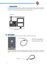
Page 16: ...pplied with the boiler will be inserted later 4 1 Manual Loading The manual loading is carried out directly by the intake of the pellets out of the bag To ensure a closed pellet load without any clogg...

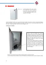
Page 17: ...of the plug in which the supplied hose must be connected which in turn must be connected to the in outlet indicated above present in the lower part of the boiler Joining in which the supplied hose sh...

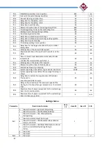
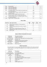
Page 18: ...haust Speed in Power 3 1600 1750 1900 rpm V06 Exhaust Speed in Power 4 1750 2100 2300 rpm V07 Exhaust Speed in Power 5 1950 2500 2700 rpm V09 Extinguishing Speed 2600 2600 2600 rpm V10 Exhaust Speed i...

Page 19: ...0 C Th78 Buffer tank Probe Safety Thermostat 80 C Th80 DHW probe Safety Thermostat 75 C Th81 Differenziale Sonda Puffer Sonda ACS 8 C Th83 DHW Thermostat Maximum Range 65 C Th85 Low Buffer tank Thermo...

Page 20: ...at D23 and A13 1 2 30 sec T46 Working time of the Valve if T42 expired 10 sec T57 Minimum duration time of Standby phase 30 sec T58 Brazier Final Cleaning in Standby 120 sec T66 System operating hours...

Page 21: ...n 1 Management Auger Brake 1 enabled A29 0 System Management in Standby for Room Thermostat 0 it does not exit for DHW demand 1 n 1 System Management in Standby for Room Thermostat 1 g it exits for DH...

Page 22: ...to pass from Modulation to Standby at the end of T43 if A13 1 2 5 C D41 Ignition Delta 20 C Menu to Restore the Default Parameters Sottomen Descrizione Contatore Totally hours Totally time operation H...

Page 23: ...n the boiler must be about 10 k at the temperature of 25 degrees C and decrease as the temperature detected to increase as the temperature drops To measure the resistance of the probe it is necessary...

Page 24: ...chimney in accordance with the UNI 10683 2012 standard Check the cleaning status of the chimney if necessary clean the same carefully by eliminating all combustion residues inside especially on change...

Page 25: ...he water not 0 degrees Celsius for example The resistance of the NTC probe that detects the temperature of the water in the boiler must be about 10 k at the temperature of 25 degrees C and decrease as...

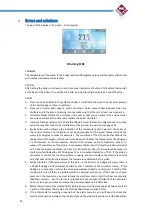
Page 26: ...e the electronic control unit that does not correctly interpret the temperature detected by the probe itself Warning Er07 PROBLEM The boiler s electronic control unit does not detect the fume extracto...

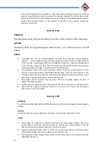
Page 27: ...the Voltage is proportional to the water pressure 0 8bar plus 0 8 volts 1 bar plus 1 Volt etc etc then replace the electronic control unit that does not correctly detect the pressure transducer signal...

Page 28: ...ssure transducer not working Measure the power voltage of the pressure transducer on contacts 37 and 39 of the electronic control unit If the Voltage is different from 5 Volts VDC replace the electron...

Page 29: ...menu measure the power voltage of the measurable cochlea engine on its contacts The voltage measured without disconnecting the engine must be 230 volts VAC If the voltage is not present do the same di...

Page 30: ...en 1 and 50 minutes the boiler when the power is restored is in the Power Recovery state performing the shutdown phase and then automatically turns it back on Other signals Sond Display status of Temp...

Page 31: ...31 REVISIONE 00 Magikal Srl Via Alpone 22 37032 Monteforte D Alpone Tel 045 6106342 Fax 045 6107773 magikal magikal it www magikal it...

Reviews: