8
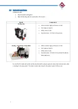
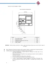
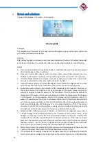
Hydraulic connection diagram as follows:
HEVO HYDRAULIC CONNECTIONS
WARNING : Provide hydraulic connection to a thermal plant able to disperse the maximum nominal thermic power of
the apparel.
After verifying the intake and outtake of the hydraulic system, according to the model that will be
installed, prepare the plant according to the following important aspects:
Use rather flexible pipes in order to make the moving of the boiler easier for any
extraordinary maintenance.
Effect the connection by using intercept valves (sphere gate valves) in order to simplify any
maintenance operation
Connect the output of the safety valve to a losing drain
For the hot water apparel, consider to install a safety valve of 6 bar.
In order to reduce limestone formation, dangerous for the pipes, if the water has a
particularly high level of hardness (more that 20°F) it is advisable to pass through a water
softener.
Simboli
Legenda
Connection
A
Return Boiler Sanitary
¾” - M
B
Flow Boiler Sanitary
¾” - M
C
Charging of the plant by manual valve
½” M
D
Return to system
¾” - M
E
Flow to system
¾” - M


