Page 43
4.3.4.
59B
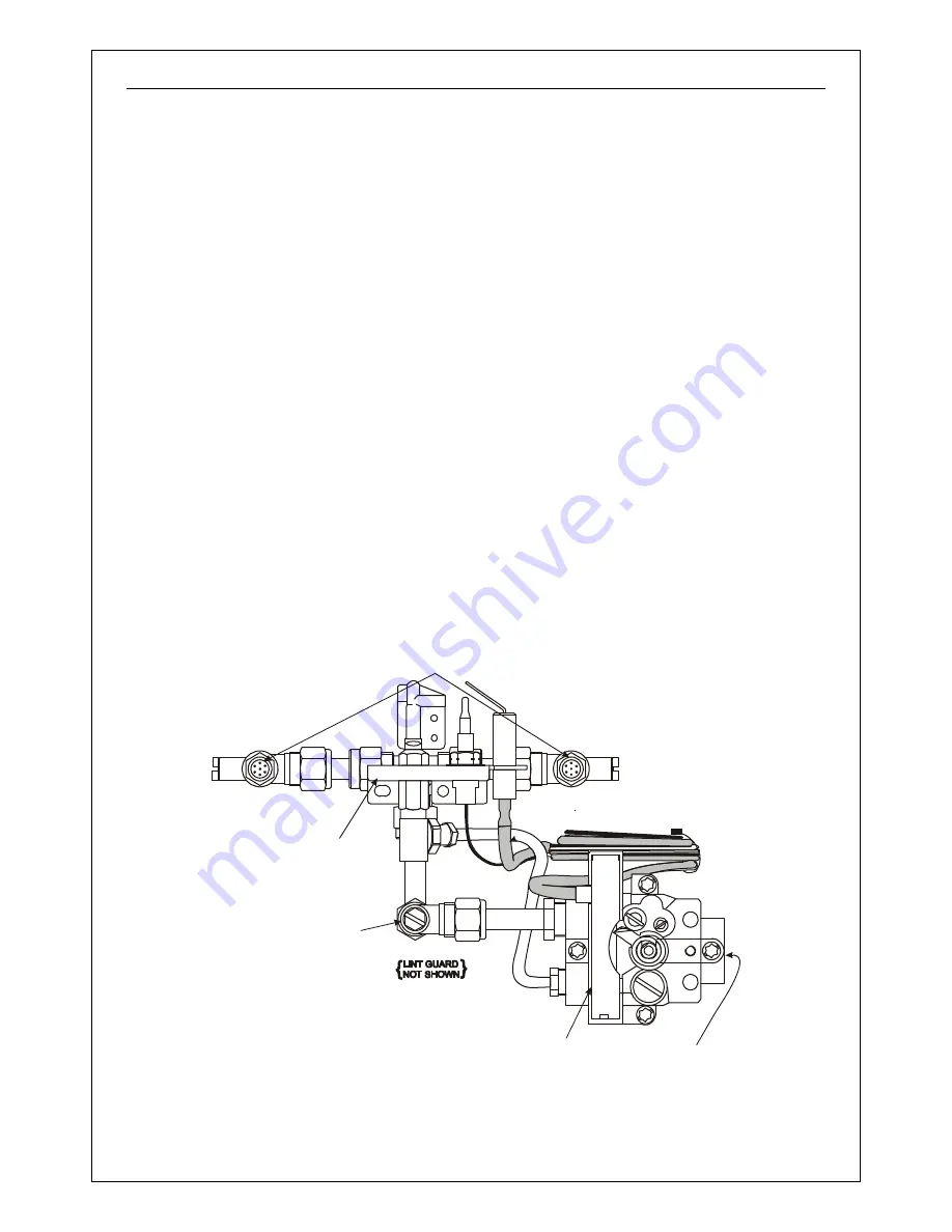
Control Valve Replacement (BM or Mertik GV34))
1. Remove the burner tray from the firebox.
2. Remove the pilot gas feed pipe nut at the
pilot. Pull out the HT cable from under
the electrode.
3. Remove the lint guard from the pilot
assembly then remove the two pilot
fixing screws.
4. Pull out the control valve cover and
remove the control valve fixing screw
located on the right hand side of the
control knob.
5. Gently pull out the injector mounting rail
from the rear of the tray. This will cause
the whole of the controls assembly to
come out in one piece. You may have to
manipulate the controls assembly to
overcome any obstructions (e.g. controls
mounting bracket).
6. Cut the cable tie. Remove the
thermocouple nut from the rear of the
control valve.
7. Undo and remove the two gas outlet
tubes on the control valve (8 mm and 4
mm tubes).
8. Pull away the old valve and replace with
new one in reverse order. Do not tighten
the nut on the gas tubes yet.
9. Refit and secure the controls assembly
onto the tray and tighten all the gas joints
taken apart during the procedure.
10. Refit the burner tray into the firebox and
follow through with commissioning and
spillage testing procedures.
PILOT
ASSY.
PRESSURE
TEST POINT
INJECTORS
GAS INLET
HT LEAD
BM CONTROL
VALVE
COVER & KNOB
NOT SHOWN
(
)
Figure 60 - Manual BM Control
Summary of Contents for ARIA
Page 8: ...Page 4 This page is left intentionally blank...
Page 28: ...Page 24 This page is left intentionally blank...
Page 42: ...Page 38 This page is left intentionally blank...
Page 53: ...Page 49 This page is left intentionally blank...
Page 54: ...Page 50 This page is left intentionally blank...
Page 55: ...Page 51 This page is left intentionally blank...


