010-200002-000
Page 10
HB IOM 1.1 2-13-2014
L
E
G
E
N
D
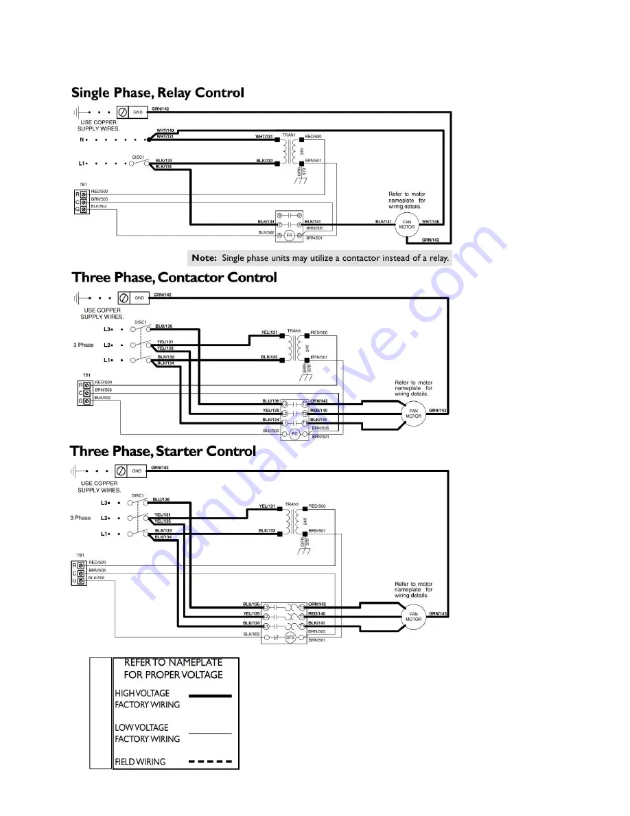
NOTES:
1.
These
diagrams
represent the factory-
installed MSS option.
If the j-box option is
provided, an arrange-
ment like this may be
field-provided
and
installed to allow the
customer's controls to
start and stop the fan.
Selection of field pro-
vided
and
installed
electrical components
is the responsibility of
the installer.
2. MSS provides sin-
gle-speed fan motor
control and includes
lockable,
non-fused
disconnect
switch,
75VA
24V
control
transformer, fan relay
or contactor or starter
(with overload if
required), low voltage
terminal
block
and
indoor enclosure.
3. Typical wiring is
shown. For exact wir-
ing, refer to the wiring
diagram provided with
the unit. 4. Factory-
installed electric heat
includes the function-
ality of the MSS, so
MSS is not required.
5. Refer to the follow-
ing pages for j-box
and electric heat op-
tions.
6. Units ordered for
208V-240V
voltage
selection are factory
wired for 240V. Field
may rewire motor and
transformer
primary
tap for operation at
208V.
INSTALLATION-ELECTRICAL (cont’d)
MOTOR START-STOP STATION TYPICAL
WIRING DIAGRAMS


