-20-
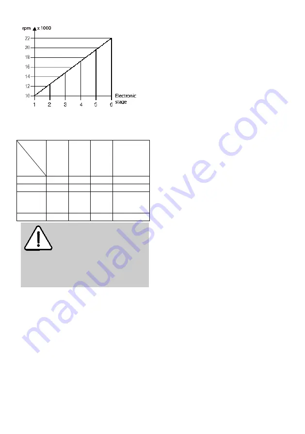
Which electronic level must be set for which milling
cutter Ø and material can be gathered from the
following table.
Bit Ø
Material
Milling
cutter
Ø 3 –
14
mm
Milling
cutter
Ø 15
– 25
mm
Milling
cutter
Ø 26–
35
mm
Recommend
ed blade
material
Hardwood
6 - 4
5 - 3
3 - 1
TCT / HSS
Softwood
6 - 5
6 - 3
4 - 1
HSS / TCT
Coated
chip
board
6 - 5
6 - 3
4 - 2
TCT
Plastic
TCT
Danger
Do not work with the LO 50 E if the
electronic system is defective, as
this may lead to excessive speeds.
A faulty electronic system can be
recognised by the lacking softstart,
by a heightened idling noise or if no
speed control is possible.
5.4 Milling depth adjustment
(see Fig. 1)
5.4.1
Clamping device
By turning handle 61 clockwise you can lock the
machine at any milling depth. If the clamping is
unscrewed, the reverse stroke into the top position is
carried out automatically.
5.4.2
Revolving depth control turret
The revolving depth control turret 10 can be used to
set three different milling depths. The longest of the
stop screws is set to the smallest milling depth while
the shortest stop screw is set to the largest milling
depth.
5.4.3
Adjustment of milling depth according to
scale
Clamp the milling cutter and place the machine
onto the workpiece.
Unscrew the clamping and contact the
workpiece surface with the milling cutter.
Afterwards clamp the machine again.
Adjust depth stop 19 up to the stop screw.
Set the top edge of the slidable needle 18 on
the depth stop to the zero point of scale 46.
Set the depth stop to the desired milling depth
and clamp it with the wing bolt 68.
Unscrew the clamping on the machine. The
reverse stroke is carried out automatically.
5.4.4
Fine adjustment of milling depth
If a delicate correction of the milling depth should
become necessary, this is done by turning the
adjusting nut 66. One turn of the adjusting nut causes
a milling depth adjustment of 1 mm (3/64 in.).
5.5 Work instructions
5.5.1
Plunge milling
A reduction plate reducing the tool opening to Ø 40
mm / 15/8 in. is mounted on the underside of the
base plate. If necessary, this reduction plate can be
removed. It facilitates machining in angular wooden
areas and reduces the risk of slipping.
During milling ensure that the workpiece is secured
and the router is resting against the workpiece with
the base plate 51 and / or the limit stops on an as
large as possible surface. Mill large depths
progressively.
Once you have set the milling cutter speed, firmly
hold onto the machine with both hands and switch on
the machine. Plunge into the material up to the limit
stop with an even feed and then lock the machine.
Only mill in counter direction.
5.5.2
Milling with parallel stop
(see Fig. 3)
The parallel stop is used to accurately guide the
machine along a straight workpiece edge.
Conversion:
Push the guide rods 73 from the rear into the
prism-shaped openings of the base plate.


