MadBoy Boomer User Manual Download Page 9

The  insert  is  a  break  point  in  the  input  channel  signal  path,  It  allows  the  signal  to  be  taken  out  from  this  BOOMER, 
through  an  external  equipment  such  as  a  Limiter,Compressor,Equalizer,  Effector,and  then  back  to  the  BOOMER,
the  input  jack  can  be  used  with  ¼  inch  phone  jack,the  signal  will  be  send  out  through  TIP  of  the  ¼  inch  phone 
jack  and  back  to  the  BOOMER  through  RING  of  the  ¼  inch  phone  jack.

DVD  OUTPUT  CONNECTIONS
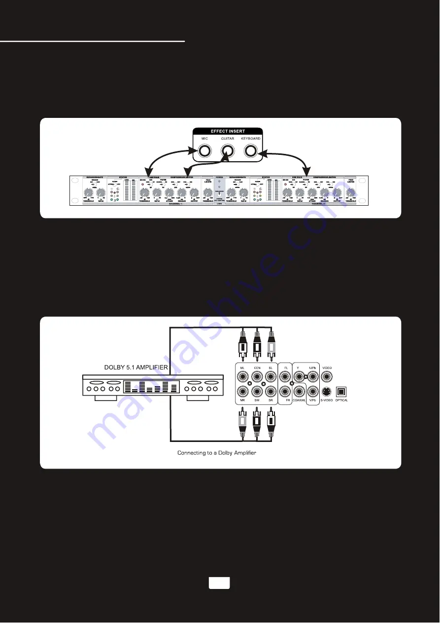
1.Connecting  to  a  Dolby  Pro  logic  amplifier 


The  BOOMER  allows  DVD  audio  output  for  5.1  or  7.1  configurations. 

        With  a  5.1  amplifier,  you  will  need  six  RCA  patch  cables.  Connect  the  plug  from  one  side  of  each  cable  to  the 
        ML,  CEN,  SL,  MR,  SW  and  SR  outputs  on  the  BOOMER.  Connect  the  plug  from  the  other  side  of  each  cable  to 
        the  corresponding  ML,  CEN,  SL,  MR,  SW  and  SR  inputs  on  your  5.1  amplifier.
        A  7.1  Pro  Logic  configuration  requires  2  additional  RCA  cables  to  be  connected  from  the  FL  and  FR  outputs  of 
        the  BOOMER  to  your  7.1  Amplifier.

2.Connecting  to  a  TV  with  component  video 

      Using  3  appropriate  component  video  cables  (usually  color  coded  red,  blue  and  green),  connect  a  set  of  plugs
      to  the  COMPONENT  VIDEO  OUT  jacks  (Y-U/Pb-V/Pr)  on  the  BOOMER  and  plug  the  other  set  of  plugs  to  the 
      COMPONENT  VIDEO  IN  jacks  (Y-U/Pb-V/Pr)  on  your  television.  On  some  TVs,    the  component  video  input
      jacks  may  be  labeled  differently  (i.e.  Pr/Pb/Y  or  Cr/Cb/Y  or  R-Y/B-Y/Y  etc.).  You  will  need  to  press  the  MODE
      button  on  the  remote  control  to  toggle  between  YUV  for  Component  Video,  and  S-Video.  You  can  only  use  the 
      MODE  button  when  there  is  no  disc  inserted  in  the  disc  tray.

6

DVD  Output  Connections

www.karaoke.at

Summary of Contents for Boomer

Page 1: ...MULTI FORMAT KARAOKE SYSTEM BOOMER USER MANUAL BOOMER www karaoke at...

Page 2: ...Music volume Adjusting the master Microphone volume Adjusting the master MUSIC EQ Changing the video mode PAL NTSC Operations Disc Mode Loading a disc Playing a disc Stopping a disc Pausing a disc Sk...

Page 3: ...Language Setup udio Setup Video Setup Speaker Setup Digital Setup Troubleshooting 18 21 23 26 27 27 27 28 28 29 Microphone Operations Turning on the Microphones Adjusting the master Microphone volume...

Page 4: ...ade or the third prong are provided for your safety If the provided plug does not fit into your outlet consult an electrician for replacement of the obsolete outlet 10 Protect the power cord from bein...

Page 5: ...gs must not be blocked or covered The openings should never be blocked by placing the product on a bed sofa rug or other similar surface This product should not be placed in a built in installation su...

Page 6: ...e Control 1 AC Power Cord 1 AAA Batteries 2 AC Input Voltage Audio Output Power AV1 audio input sensitivity Video input sensitivity Microphone Input Sensitivity Keyboard Guitar Input Sensitivity Video...

Page 7: ...deo monitor with a RCA video input 1 Connect one end of the RCA video cable to the yellow Video Out on the rear panel of the BOOMER 2 The BOOMER has two RCA type VIDEO OUTPUT jacks for connecting to T...

Page 8: ...NNECTIONS Connect one end of the L R red white RCA cable to the red and white audio outputs labeled AUDIO OUTPUT 1 2 on the rear panel of the BOOMER Connect the other end of the L R red white RCA cabl...

Page 9: ...om the other side of each cable to the corresponding ML CEN SL MR SW and SR inputs on your 5 1 amplifier A 7 1 Pro Logic configuration requires 2 additional RCA cables to be connected from the FL and...

Page 10: ...an optical connection as those cables eliminate the possibility of EMI electromagnetic interference has 5 1 or 7 1 channel RCA inputs you can use the 5 1 or 7 1 channel output jacks on the BOOMER AV i...

Page 11: ...plug into either the MIC 1 or 2 jack on the BOOMER 2 To connect MICROPHONES via XLR mic cables attach the XLR female end of the cable into the male three prong jack located at the base of your handhel...

Page 12: ...put channel or use the SELECT button on the front panel to cycle through the input channels 2 Once the desired input channel is selected playback can begin Adjusting the master Music volume The master...

Page 13: ...l Skipping tracks chapters 1 Use the PREV and NEXT buttons on the remote control or front panel to skip tracks chapters 2 Press the PREV button to skip to the previous track chapter 3 Press the NEXT b...

Page 14: ...size 4X Zooms in 4X the original size Note when you try to play MPG and JPG file include the MPG and JPG file on DISC USB SD 1 Press the ZOOM button on the remote control to enter ZOOM mode 2 Use the...

Page 15: ...Last Memory is highlighted and press up so that On is highlighted 4 Press ENTER on the remote control to confirm the selection 5 Press SETUP again on the remote control to close the Setup menu 12 Oper...

Page 16: ...he graphic display on the front panel display NO DISC and then insert USB and SD CARD to the USB and SD CARD jacks then begin to load the media sources from USB or SD CARD 1 Using the USB Input Plug a...

Page 17: ...cord Press the DVD button on the remote control it will apprears the a frame Fig B and use the Directional buttons on the remote control to select USB or SD card and then press ENTER button to enter U...

Page 18: ...D Card REC Operartions 3 Copy songs in MP3 discs to USB or SD card Insert a MP3 disc into the disc tray Press PLAY on the remote control or on the front panel to start play the disc Insert USB or SD c...

Page 19: ...its own volume control located on the front panel of the BOOMER Each one can be adjusted separately providing a great sounding vocal mix 2 Turn the MIC 1 VOL and or MIC 2 VOL control clockwise to rais...

Page 20: ...er clockwise to DECREASE level DELAY This control adjusts the amount of time between each echo repeat Turn clockwise to make the time shorter and counter clockwise to make the time longer Adjusting th...

Page 21: ...ise to decrease the MUSIC VOLUME 9 REMOTE SENSOR This sensor receives infrared signals transmitted by the REMOTE CONTROL transmitter Note Obstacles located between the remote control and remote sensor...

Page 22: ...disc player Raises the musical key a half step each time it is pressed Resets the musical key to its original key b Lowers the musical key a half step each time it is pressed NOTE Key controller will...

Page 23: ...ECHO effect As DELAY adjusts the total begin to end length of each echo interval the more DELAY that is applied the longer each ECHO interval will take to complete Turn control clockwise to INCREASE...

Page 24: ...s used as the main left output in a stereo system The MR jack is the same as the FR jack and is used as the main right output in a stereo system 6 COMPONENT VIDEO OUTPUT These jacks output VIDEO to a...

Page 25: ...jacks on your external AV devices 14 VIDEO OUT 1 2 JACKS RCA These jacks are for connecting the BOOMER s VIDEO OUTPUT to TV or DISPLAY devices Connect RCA type patch cables from these jacks to the VI...

Page 26: ...the VCD must be a VCD 2 0 disc 13 Stop button Stops disc playback in standby mode when pressed once and completely stops disc playback when pressed twice 14 Play button Plays a disc that is stopped or...

Page 27: ...2X 1 3X and 1 4X on the video during disc playback 31 OSD button Cycles through the different On Screen Display options See the Operations section in this manual for detailed instructions on selectin...

Page 28: ...ce the batteries The maximum operational distance between the remote control and the sensor is approximately 25 feet If the remote only operates at shorter distances it is time to replace the batterie...

Page 29: ...al to determine which type of video it supports You can choose between INTERLACE YUV P SCAN YPBPR or S VIDEO 4 TV TYPE This menu actually refers to TV display mode Choose between 4 3PS for Panoramic S...

Page 30: ...output standard analog audio simultaneous with digital output by using the RCA L R outputs and Coaxial output When connecting the BOOMER to an external sound system with digital inputs choose between...

Page 31: ...Set this based on the size of your front speaker LARGE SMALL DIGITAL SETUP 1 OP MODE LINE OUT Compresses the input signal and lowers the volume for use in quieter settings for example at night time R...

Page 32: ...r monitor is working correctly 4 The disc does not play Make sure the disc is inserted correctly label side up Make sure the disc is clean and not scratched If using a CD DVD R RW try using a differen...

Reviews: