Owner
’s Manual
19
Owner’s Manual
Front LED Mode –
There are two horizontal LED
bars on the front of each SRM | V-Class loudspeaker. One
bar is located near the bottom and the other near the top.
Here is where you decide if you want the front LED
on, off or sig. When illuminated, push the speaker
control knob to select between the three choices.
The three front LED modes are as follows:
• On [Default] –
The LEDs illuminate in all their
glory.
• Signal –
The LEDs illuminate when there is signal
at the outputs.
• Off –
The LEDs do not illuminate; they are turned
off and SRM | V-Class is in ‘stealth’ mode.
Like the previous sub-menus, configuration also
has a left-facing arrow. Illuminating and selecting
this simply returns you to the menu.
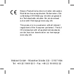
LED Color –
Here is where you decide what color
you want the front color LED. When illuminated,
push the speaker control knob to select between
the three choices.
The three LED colors to choose from are:
• Green [Default] –
The LEDs illuminate green.
• White –
The LEDs illuminate... you guessed it.
White!
• Multi-color –
The LEDs switch between green,
white and off in five second intervals. This
is typically used in retail situations, but feel
free to use it yourself!
Multi-color may only be selected if the front
LED mode is set to on. It will not work if set
to signal or off.
Illuminating and selecting the left-facing arrow
returns you to the previous screen.
CONFIGURATION
ABOUT/RES...
LED COLOR
LCD SCREEN
BT SETTINGS...
LOCK...
HI
DIM
OFF
GRN
WH MUL
ON
OFF SIG
CH1 IN
LINE
MIC
CH2 IN
LINE
HI-Z
FRONT LED
CONFIGURATION
ABOUT/RES...
LCD SCREEN
BT SETTINGS...
LOCK...
HI
DIM
OFF
GRN
WH MUL
ON
OFF SIG
CH1 IN
LINE
MIC
CH2 IN
LINE
HI-Z
FRONT LED
LED COLOR
LCD Screen –
The fifth configuration setting
that may be changed is the brightness – or lack
thereof – of the LCD screen.
There are three choices: hi, dim and off.
Hi or dim LCD screen brightness is required
for certain aspects of the set-up options.
Illuminating and selecting the left-facing arrow
returns you to the previous screen.
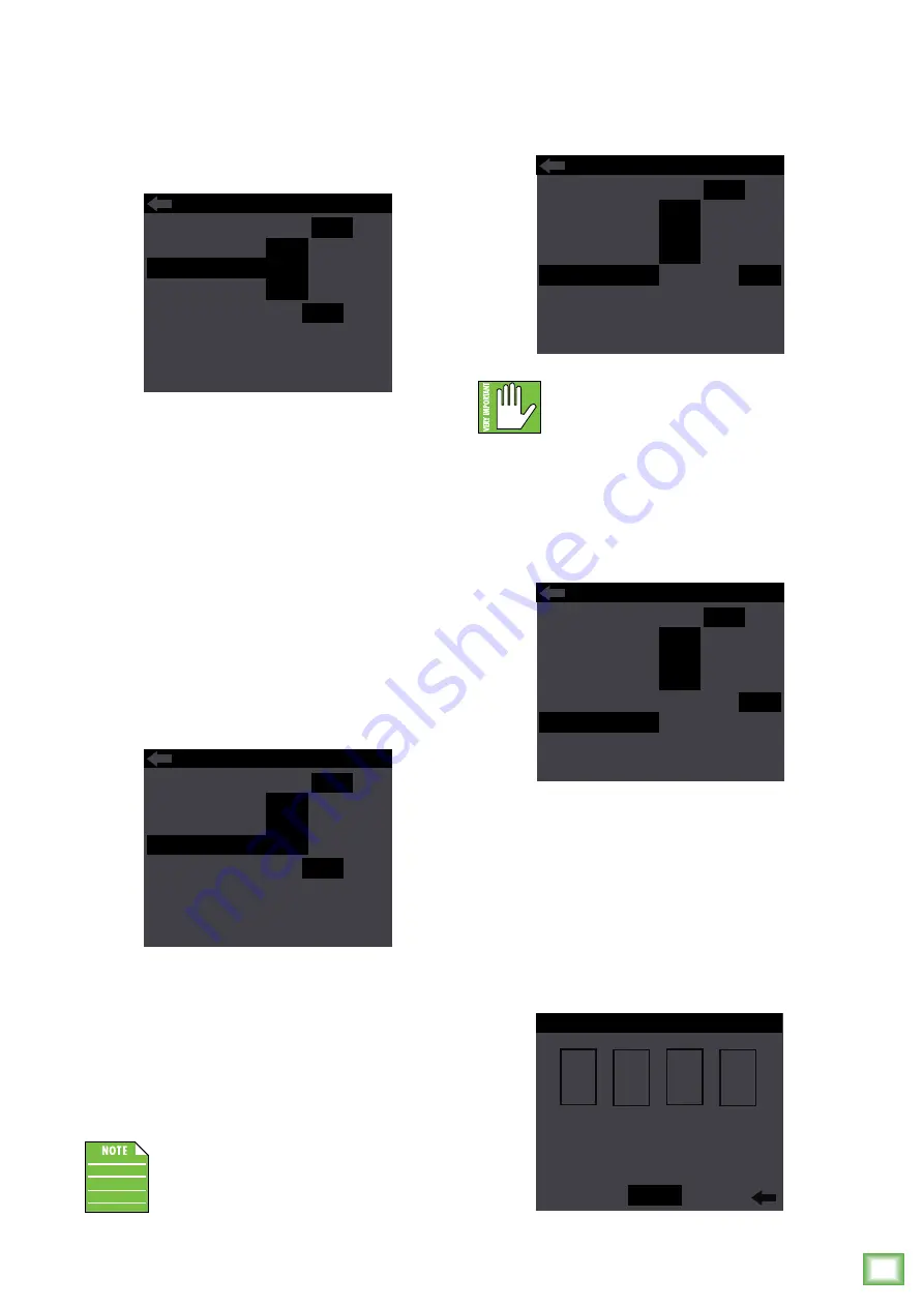
Lock... –
This is where to lock and unlock the
interface with a secret 4-digit numeric password.
Locking –
Push the speaker control knob to enter
lock mode. From here, rotate the speaker control
knob until the first number you desire is illuminated
and press to select. Follow the same procedure
for the next three numbers.
As seen below, we decided to go with 1-9-8-4
because we’re “fans” of George Orwell.
Notice how “lock” appears and is illuminated.
Push the knob again to confirm the lock.
No further changes may be made until the control
access is unlocked.
CONFIGURATION
ABOUT/RES...
BT SETTINGS...
LOCK...
HI DIM
OFF
ON
OFF SIG
CH1 IN
LINE
MIC
CH2 IN
LINE
HI-Z
FRONT LED
LED COLOR
LCD SCREEN
GRN
WH MUL
CONFIGURATION
ABOUT/RES...
BT SETTINGS...
HI DIM
OFF
ON
OFF SIG
CH1 IN
LINE
MIC
CH2 IN
LINE
HI-Z
FRONT LED
LED COLOR
LCD SCREEN
GRN
WH MUL
LOCK...
CONTROL ACCESS
DEL
1 2
1
3 4 5 6 7 8 9 0
8
9
4
LOCK