


Owner's Manual
23
46
47
49
52
55
48
50
51
53
54
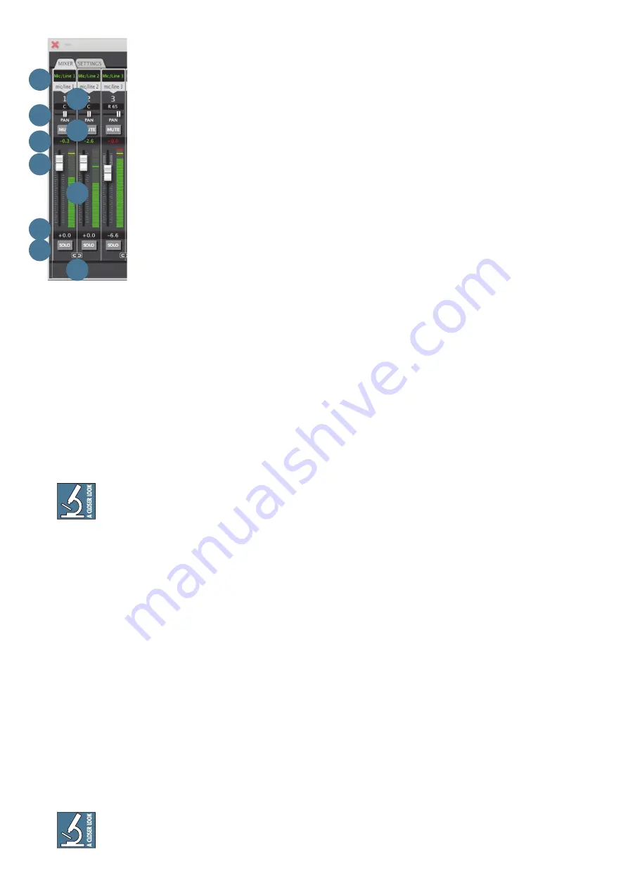
Input Channel Strip Features
Top to bottom of each channel strip,
here are the features of each input
channel in detail:
46. SOURCE
At the top of each channel's input
are that channel's input source as
well as a customizable name for that
source. For example, input 1 is
denoted as "mic/line 1" in two places
at the top of each channel by default.
At the very top (in green) is a
customizable text block.
Double-clicking in this space allows
the input name to be changed.
Let's say the signal feeding the physical mic/line input
1 is the kick drum. Feel free to rename this input to
"Kick" for the current active session.
Furthermore, if you want the kick drum to appear on
a different input channel than input 1, simply click on
the input source (above the channel number you want it
on) and a dropdown list will appear so any input may be
moved to any input channel on the mixer; the customiz-
able input name follows suit.
Likewise, any input channel may have "no input" per
the available options in the input dropdown list.
Do not route the same input (e.g. mic/line
1) to multiple inputs on the mixer. Routing
two of the same signal to a given output is
known as double-bussing. This only serves to make the
signal louder. (Of course, this also bears the possibility
of octadecatuple-bussing – 18 cloned inputs routed to
a single mixer output – which is just plain unnecessary
and possibly illegal in some states).
47. CHANNEL NUMBER
Below the input source [46] is a fixed channel
number display. This is the mixer channel that is
currently being monitored and/or edited.
48. PAN
Below the input channel number [47] is the pan
section. The horizontal pan slider allows each channel
to be panned anywhere from hard left to center to hard
right and anywhere in-between. The read-only display
above the pan slider indicates the L/R pan percentage,
with "C" representing center.
To re-center any pan slider, simply double-
click anywhere on the pan slider track
and – bam – centered!
49. MUTE
Selecting this button will mute the channel's output
to the main fader of the output tab that is currently
being edited. However, all level indicators will continue
to display input levels. When a channel is muted, this
button turns red. Input channel mutes are post-fader
and pre-solo.
50. PEAK LEVEL
This numeric display shows the hottest peak level
that the channel has received within a tenth of a decibel
(until the peak level area or the input meter itself is
double-clicked to clear, or until clear peaks [57] is
pressed, which does exactly what it states – it clears all
peaks). When inputs have clipped, both the input level
and the top of the input meter [52] will turn red to
indicate that a clip has occurred. Input peak levels are
pre-fader.
51. CHANNEL FADER
The channel fader controls the amount of signal being
sent to the current selected output tab (and, in turn,
physical output of the product). The gain range of fader
adjustments is +6 dB to –infinity dB, and the fader may
be double-clicked to return to 0 dBFS (unity gain).
Input channel faders are post-input metering.
52. METER
This graphic display shows the current input level
in graduated increments. (Each segment represents a
half-decibel at the top end of the meter; the precision
of the segment drops to two decibels per segment at the
bottom.)
Most of the meter is green (when receiving input).
Yellow is used NOT to indicate that the signal is above
0 dBFS, but rather that it is within 3 dB of clipping.
When inputs have clipped, both the peak level [50]
and the top of the input meter will turn red to indicate
that a clip has occurred. This may be cleared by double-
clicking in the peak level area, the meter, or by selecting
clear peaks [57]. Input meters are pre-fader.


