52
SeCtion b
SoFtware Manual
RetuRn to toC
MaCe HydRoMaCe 3000
Product Manual
53
RetuRn to toC
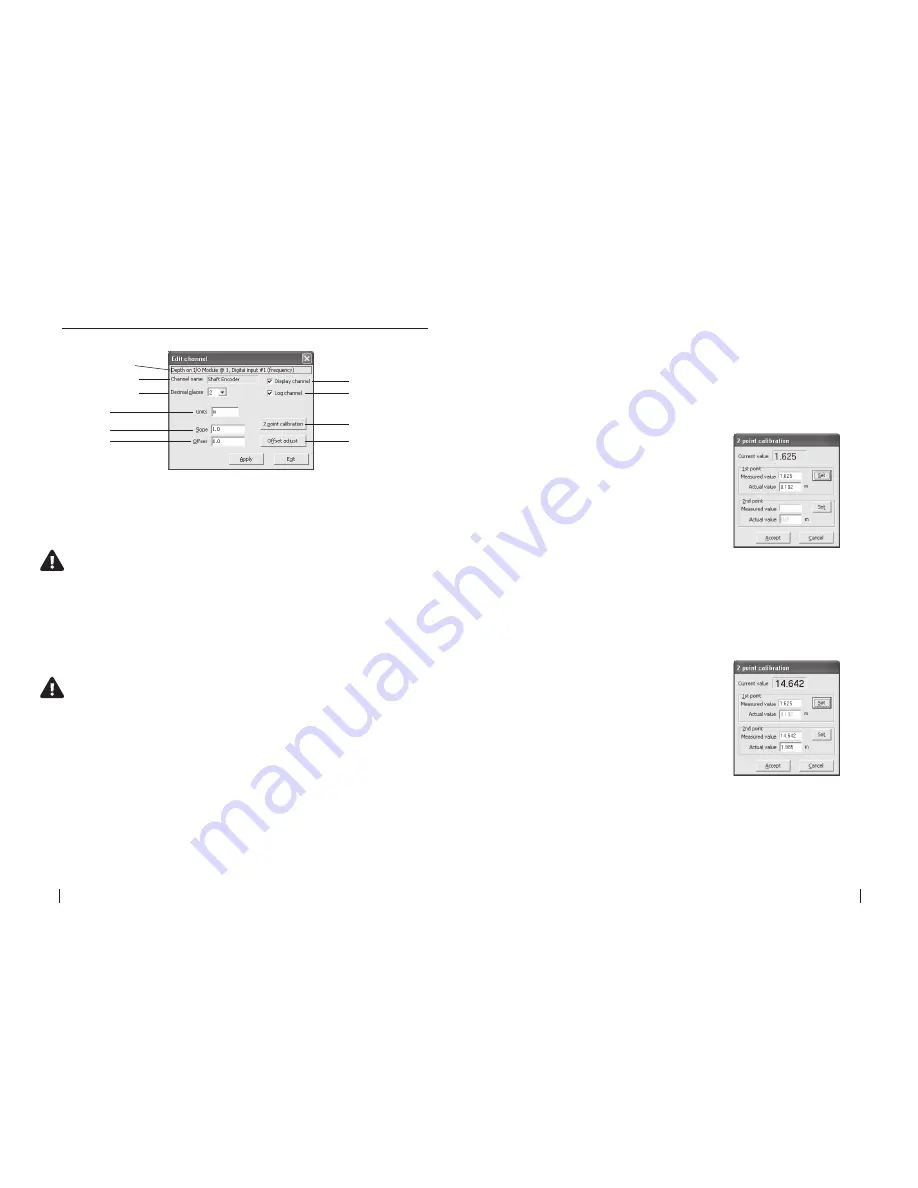
21.3.1 Edit “Depth” channel type
Channel path
Display channel
Channel name
Log channel
2 point calibration
Offset adjust
Decimal places
Slope
Units
Offset
Channel path
This describes the channel type and the module input source.
Channel name
This is the name given to the channel by the user when setup.
NOte: this name will also show on the hM 3000 LCD screen if the Display
channel check box is ticked.
Decimal places
The user can set the number of decimal places (0, 1, 2, 3) using the drop down list
box. These decimal places will be shown in both the data file and the LCD.
Units
This sets the units on the logged value. This is a text field and is user defined.
NOte: If a “Velocity or Depth” channel type is configured on a
“Frequency, Voltage or Shaft encoder” input the Units are defined according
to the “System settings”
Display channel
If this check box is ticked then this channel will be displayed on the HM 3000 LCD.
Log channel
If this check box is ticked then this channel will be logged in the data file.
Slope and Offset
If the user has a sensor with known slope and offset characteristics, they may
be entered directly into the unit configuration. Alternatively, the user should
perform a 2-point calibration or calculate the slope and offset values of the
sensor as described on the following pages.
2-point calibration
To correctly calibrate an environmental sensor it is important to calibrate
it over its useful range. For example, if a depth sensor has a range of 0 - 2
metres but you only wish to use it to measure the range 0.1 metres to 1.2
metres, you should re-calibrate it across the reduced range.
1.
Click
“2-point calibration”
from the
“Edit channel”
dialogue box and the
“2 point
calibration”
dialogue box appears.
The
“Current value”
from the sensor (in this
case a depth sensor with frequency output) is
displayed at the top of the window and is updated
approximately once per second.
2.
To carry out a two point calibration, prepare the
measurement set up for the first calibration point
(either the sensors upper or lower range limit).
3.
When the
“Current value”
has stabilised, click on the
“Set”
button in the
“1st point”
box. The
“Current value”
is copied to the
“Measured value”
field of the
“1st point”
box and the
“Actual value”
field is enabled.
4.
Enter the sensors actual value (in this case depth) in
the
“Actual value”
field.
5.
Prepare the measurement set up for the second
calibration point (the opposite sensor range limit
from that used in point 2 above). For example, if
you used the upper range limit in point 2, now use
the lower range limit.
6.
When the
“Current value”
has stabilised, click
on the
“Set”
button in the
“2nd point”
box. The
“Current value”
is copied to the
“Measured value”
field of the
“2nd point”
box and the
“Actual value”
field is enabled.
7.
Enter the sensors actual value (in this case depth) in
the
“Actual value”
field.
8.
Click on the
“Apply”
button to calculate the new
slope and offset parameter values for the associated
channel. Clicking on the
“Cancel”
button terminates the
procedure without altering the parameter values.


