18
SeCtion a
Hardware Manual
RetuRn to toC
RetuRn to toC
MaCe HydRoMaCe 3000
Product Manual
19
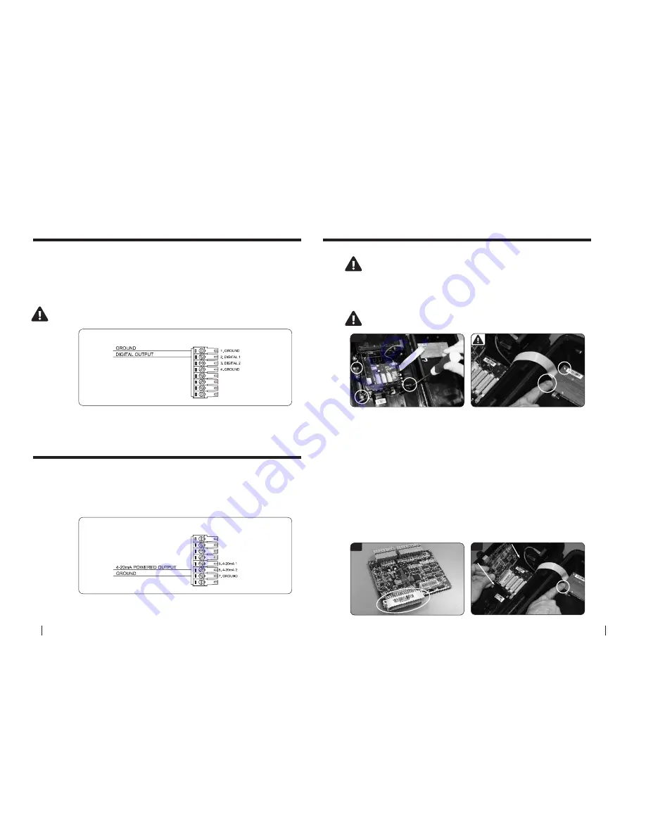
DIGITAL OUTPUT DIAGRAM
4-20mA OUTPUT DIAGRAM
DIGITAL OUTPUT DIAGRAM
4-20mA OUTPUT DIAGRAM
10.0 Wiring digital outputs
11.0 Wiring analogue outputs
Digital Output
Each I/O card provides up to two digital outputs for sending pulses to
devices such as water samplers and/or data loggers. The digital output
terminals available on each I/O card are shown in the diagram below.
4-20mA Output:
Each I/O card provides up to two 4-20mA outputs for sending signals to
devices such as SCADA systems and/or PLC’s. The 4-20mA output terminals
available on each I/O card are shown in the diagram below.
NOte: the pulse output consists of a 50 millisecond pulse with a 50
millisecond space between pulses
12.0 Installing additional cards
Users are advised to download data and stop the hM 3000 prior
to installing additional cards
1.
Open the Series3 enclosure and remove the three screws
(using a #2
Phillips screwdriver)
fastening the PCB clamping bracket. Take care not to drop
screws in the box as damage may occur to the circuitry.
IMPORTANT: Before removing card from packaging you MUST earth
yourself by touching one of the screws on the display module
1
3
3.
Remove the MACE Series3 card from its packaging. Position the new card
in your hand such that the large cream 48-pin connector is facing down and
aligned with the mating connector on the backplane PCB.
4. earth yourself again.
Your finger must remain earthed on the screw
whilst carefully inserting the card into any spare slot. Take care to align the
pins of the two connectors together. There is a slot at the top of the card
area that helps the alignment process. Ensure that the card is contained
within this slot and press down firmly to ensure that it is seated fully.
5.
Replace the PCB clamping bracket ensuring that the slots in the underside
of the bracket are aligned with the tops of all the cards. Fix the bracket into
place with the 3 screws.
DO NOT over tighten the screws.
6.
Connect to the instrument with a PC and configure the card using FloCom
+
as detailed in the software section of this manual.
4


