Installation Procedure, LXE Models 6723 Bridge & 6730 AP (non-RoHS)
95
E-EQ-NEMARG-F
NEMA Type 4 Enclosure Reference Guide
159089-0001 Rev. C
Page 13 of 15
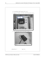
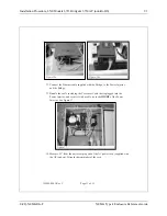
38. Plug the other end of the cable into the AP Power Brick. See figure 20.
39. Bundle Crossover Cable and the power cord together and secure them with an
8” nylon cable tie. Pull it tight and trim. See figure 20.
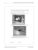
40. Measure 19” from the universal plug end of the AC power cord (supplied with
the Bridge) and cut. Discard the remainder of the cord.
41. Remove at least 2” inches of the outer covering from the cut end of the cord.
See figure 18.
42. Remove 0.4” (10 mm) of the insulation from each conductor.
43. Insert the conductors into the terminal block on the
LEFT
side. Neutral
(marked blue), Live (unmarked), Ground to Ground (marked green). See
figure 19.
44. Route the cord around the
LEFT
side of the AP. See figure 21.
45. Plug the other end of the cable into the Bridge Power Brick. See figure 21.
Figure 20
AP Power
Brick
Crossover and
Power cord
secured


