


6-1
6
Parameter description
01-MODE Operating mode [Decimal]
MODE determines the control options for the inverter and defines the
effective operating level e.g. for the K
EY
P
AD
KP100.
The parameters are allocated in 3 levels.
In Level 1, the most important parameters for commissioning are to be
found.
Level 2 enables in addition to the alteration of the parameters contained
in Level 1, access to further parameters as well as special and control
functions, such as data set changeover or programming the control
outputs for example.
Level 3 is reserved for interface parameters (SIO mode) and special
parameters
(further information about this can be found in the information
booklet "Parameter description - Total range").
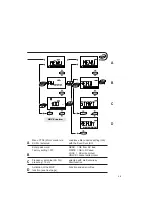
01-MODE = 1
-> Operating level 1 Commissioning level
01-MODE = 2
-> Operating level 2 Operating and control function
01-MODE = 3
-> Operating level 3 Interfaces and special param.
01-MODE = 0
-> Operating level 0 Only SIO-mode
6.1
Reference input
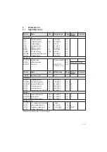
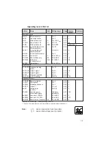
04-FSSEL Frequency reference selector
Offers the selection between various types of reference (analog, frequency
or PWM-signal) and their origin (K
EY
P
AD
, SIO,...).
04-FSSEL
Function
0
Analog input active, adaption via J1 ... J6
1/2
Not active
3
FSIN as frequency input 0 to 1 kHz active
4
FSIN as frequency input 0 to 10 kHz active
5
FSIN as PWM input 20 to 100% active
6
FSIN as PWM input 0 to 100% active
7
FSIN not active, reference via KP100 (CTRL- menu)
8
Reference via interface
9 to 16
Reference input see following
17 to 22
Correction of the analog reference via S1IND/S2IND
(MOP-function active)
23
Inverted analog input, 10 V = FMIN, 0 V = FMAX
Summary of Contents for SMARTDRIVE VF1000 M Series
Page 10: ...A 8 A 4 Manufacturer s declaration for frequency inverter ...
Page 11: ...A 9 ...
Page 13: ...A 11 ...


