


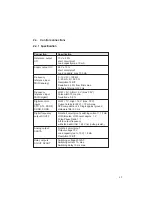


2-3
Caution:
The connected mains may not exceed the following effective
voltages for all devices in this manual:
VF1205M... VF1207M
L1 ->
N
230VAC
L1 ->
230VAC
VF1404M... VF1410M
L1 ->
L2 ->
L3
460VAC
L1/L2/L3 ->
270VAC
2.2
Fault transmission/interference immunity (EMC)
All S
MART
D
RIVE
frequency inverters of the M series fulfil the requirements
of EMC interference immunity in industrial areas according to the EC
Directives/European Norms 89/336/EEC, prEN 50 062-2 (for this also see
CE acceptance test in Chapter A).
The certified EMC testing of the fault resistance of the inverter is according
to prEN 50082-2/01.93.
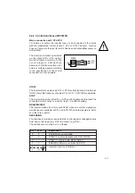
It is essential the following instructions are observed when installing
an inverter in a machine for example, so that the EMC statute is
complied with:
⇒
The motor cable, the mains cable and the control cables should be
separated from each other and screened.
⇒
The device should be screwed onto a well
grounded mounting plate. A toothed washer
(Z) must be placed under each of the fixing
screws of the device, so that the inverter
housing has good contact to the mounting
plate.
⇒
The screen of the mains and motor cable is
clamped in place directly with the conductive
cable clamps labelled in the circuit diagram.
⇒
The screen of the control cables is also directly clamped in place with
the cable clamps labelled in the circuit diagram. As long as the sum of
diameters allow it, several control cables can be clamped under one
cable clip.
⇒
The terminal box of the motor must be HF-proof. It must therefore be
made from metal or metallised plastic.
⇒
The bushing for the motor cable at the terminal box should be made
from a conductive cable screw connection with screen linkage.
,
,
Z
Summary of Contents for SMARTDRIVE VF1000 M Series
Page 10: ...A 8 A 4 Manufacturer s declaration for frequency inverter ...
Page 11: ...A 9 ...
Page 13: ...A 11 ...


