background image

4-10

CDA3000 Operation Manual

4  Commissioning

Input signals

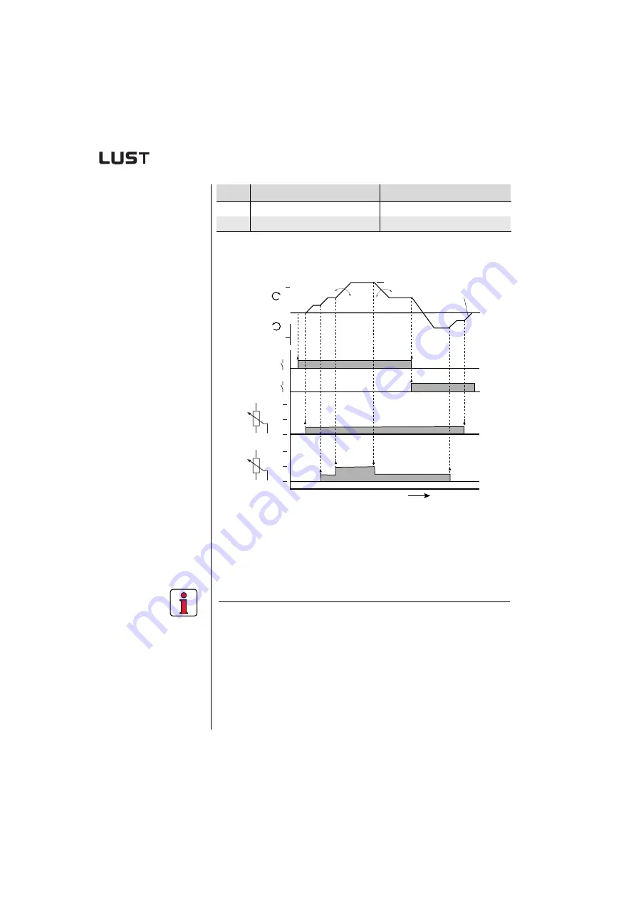
Figure 4.4 Example of a driving profile for two directions with correction 

reference (R2), 152-ASTER = ROT_2

FOR setting

FOR is preset, and requires no further optimization for standard
applications.

Note:

For more detailed information on optimizing

 the speed control loop

 refer to the CDA3000 Application Manual.    

6

Brake drive by opening start contact. Drive brakes down to standstill.

7

Open ENPO contact.

Safely disables power stage.

Commissioning is completed.

Step

Action

Note

t [ms]

   0

   0

   1

10 V

FMAX

  5 V

R1

  0 V

f [Hz]

STL

   0

   1

STR

10 V

  5 V

R2

  0 V

FMAX

303-FMAX1

592-DECR1

590-ACCR1

594-STPR1

Summary of Contents for CDA32.004

Page 1: ...D CDA3000 Umrichtersystem 750 W 132 kW DE EN FR IT ES Betriebsanleitung Operation Manual Manuel d utilisation Istruzioni di esercizio Inverter Drive System Syst me variateur Sistema invertitore...

Page 2: ...trie bsanle itung beach ten WARN ING capac itor dissch arge time 3 minute s Pay attenti on to the operat ion manua l ATTEN TION temps de decha rge du conde nsteur 3 min observ er le mode d mpl oi X1 L...

Page 3: ...tem very quickly and easily Guide to quick starting 2 Simply follow the step by step tables in sections 2 3 4 Experience Plug n Play with the CDA3000 And away you go 1 Safety 2 Mechanical installation...

Page 4: ...KEYPAD KP200 Adaptation of the drive system to the application CANLust Communication Module Manual CANopen Communication Module Manual PROFIBUS DP Communication Module Manual Project planning install...

Page 5: ...pplied Rotating parts Hot surfaces Your qualification In order to prevent personal injury and damage to property only personnel with electrical engineering qualifications may work on the device The qu...

Page 6: ...fundamentally not fail safe The company setting up and or operating the machine or plant is itself responsible for ensuring that the drive is rendered safe if the device fails EN 60204 1 DIN VDE 0113...

Page 7: ...e vicinity no drill chippings screws or foreign bodies drop into the device the vent openings are not covered over The device may otherwise be damaged 2 2 Mounting variants Step Action Comment 1 Refer...

Page 8: ...ponents such as the mains filter line choke etc on the backing plate Mains filter max 20 cm below the inverter module 4 Continue with the electrical installation in section 3 Note the following points...

Page 9: ...325 305 380 A 40 40 80 130 215 265 340 C 235 260 320 360 555 485 D 4 8 4 8 6 9 Screws 4 x M4 4 x M4 4 x M5 4 x M8 E 0 50 E1 with module 45 F 100 1001 G 300 400 1 Additionally allow enough space at th...

Page 10: ...2 Clean the contact surface and coat it thinly and evenly with heat transfer compound The contact surface must be metallically bright 3 Mount the inverter module vertically on the backing plate or coo...

Page 11: ...0 200 H height 215 240 300 D depth 120 145 150 A 50 85 135 185 C 205 230 200 C1 100 D 4 8 5 5 Screws 4 x M4 6 x M5 E 0 0 E1 with module 45 15 F 1001 G 300 1 Additionally allow enough space at the bott...

Page 12: ...5 kW CDA34 005 Cx x 80 W 112 W 0 05 650x460mm 0 3m 45 C1 40 C2 2 2 kW CDA34 006 Cx x 106 W 148 W 0 05 An additional cooler is required to supply adequate cooling Project planning notessee appendix A 4...

Page 13: ...ponents such as the mains filter line choke etc on the backing plate Mains filter max 20 cm below the inverter module 4 Continue with the electrical installation in section 3 Note the following points...

Page 14: ...igure 2 3 Mounting clearances see Table 2 6 Dimensions of breakthrough BG3 BG4 BG5 W width 75 125 175 H height 305 305 305 Table 2 5 Breakthrough for push through heat sink dimensions in mm F E E1 G F...

Page 15: ...8 T2 135 A 90 140 190 A1 80 100 C 320 C1 200 D 4 8 4 8 4 8 Screws 8 x M4 10 x M4 10 x M4 E 10 E1 with module 20 F 1001 G 300 1 Additionally allow enough space at the bottom for the bending radii of th...

Page 16: ...2 10 CDA3000 Operation Manual 2 Mechanical installation...

Page 17: ...ng resistor RB 3 9 3 7 Control connections 3 10 3 7 1 Choice of terminal assignment 3 11 3 7 2 Specification of control terminals 3 12 3 7 3 Terminal assignment 1 3 13 3 7 4 Terminal assignment 2 3 14...

Page 18: ...L N L1 K1 K1 L2 L3 L1 N PE RB M 3 FN 1 7 1 2 6 8 4 5 3 Key Explanation 1 Line choke1 Reduces the voltage distortions in the system 2 Mains filter1 2 Suppresses line borne interference emission 3 Braki...

Page 19: ...ins connection 10 mm Use grounding lead PE cross section according to cross section of mains leads 2 Also connect the grounding lead connections of all other components such as the line choke filter e...

Page 20: ...er module For inverter modules BG1 5 0 37 15 kW there is an accessory shield ST02 ST04 or ST05 permitting simple clip mounting with all round contact For inverter modules BG6 8 22 132 kW we recommend...

Page 21: ...g For thermal monitoring of the motor coil a thermistor PTC may be connected to terminals X3 and The type used must be set during commissioning in parameter 330 MOPTC factory default setting is off At...

Page 22: ...it breakers trip characteristic C to cut the mains power to all poles of the inverter To protect the line in accordance with VDE636 part 1 Connection of the inverter module via a line choke with a sho...

Page 23: ...tem After a rest phase of a few minutes the device is ready to start once again TN network and TT network Permitted without restriction IT network insulated center point Not permitted In the event of...

Page 24: ...project engineer Inverter module Device connected load kVA Max possible wire cross section of terminals mm Recommended mains fusing gL A CDA32 004 1 7 2 5 1 x 10 CDA32 006 CDA32 008 CDA34 003 CDA34 0...

Page 25: ...istor may be connected to terminals X1 L and RB this would damage the inverter module Attention At warning message excessive temperature at inverter heat sink the connected device must be separated fr...

Page 26: ...o the inverter module refer to section 4 6 3 Choose a terminal assignment see 3 7 1 Choice of terminal assignment 4 Wire the control terminals with shielded cables The only essential signals are the E...

Page 27: ...l So that a current overload shut off or uncontrolled movements can occur Typical applications Control method Terminal assignment Continued on Project planning and commissioning are already complete L...

Page 28: ...ower stage enable High level Specification as ISDxx Digital outputs OSD00 Short circuit proof PLC compatible Imax 50 mA Protection against inductive load High side driver OSD01 Short circuit proof wit...

Page 29: ...ntact for Ready message 19 OSD02 18 OSD02 17 DGND Digital ground 16 OSD01 Reference reached message 15 OSD00 Output for motor holding brake 14 DGND Digital ground 13 UV Auxiliary voltage 24 V 12 ISD03...

Page 30: ...20 OSD02 Relay contact for Ready message 19 OSD02 18 OSD02 17 DGND Digital ground 16 OSD01 Standstill message 15 OSD00 Reference reached message 14 DGND Digital ground 13 UV Auxiliary voltage 24 V 12...

Page 31: ...peed input for two directions with speed correction Encoder evaluation 152 ASTER ROT_2 X2 Des Function 20 OSD02 Relay contact for Ready message 19 OSD02 18 OSD02 17 DGND Digital ground 16 OSD01 Refere...

Page 32: ...est possible value is 1024 pulses per rev binary 210 Minimum motor speed Formula for calculating the minimum motor speed depending on the encoder lines per revolution so that one pulse of the encoder...

Page 33: ...cians who have undergone instruction in the necessary accident prevention measures 4 1 Choice of commissioning Standard commissioning The device can be put into operation with its factory settings wit...

Page 34: ...4 4 The same applies to commissioning of special motors such as reluctance synchronous or HF motors Please consult your project engineer Step Action Note 1 Connect the mains power supply to the invert...

Page 35: ...ick slow jog driving profile for two directions Output signals of terminal assignment 1 152 ASTER DRV_1 Figure 4 2 Output signals dependent on driving profile H1 Reference reached K1 Motor holding bra...

Page 36: ...y FMAX 50Hz at reference value R1 10 V Acceleration ramp1 Deceleration and stop ramp1 If this is not possible change the parameters with the KEYPAD 3 Press the start enter key once to enter subject ar...

Page 37: ...oject engineer Figure 4 3 Signal characteristic dependent on driving profile ASTER ROT_6 Reference S2 ISD03 S1 ISD02 ISA00 Analog reference at input ISA00 R1 0 0 active Table frequency 601 FFTB1 FS 10...

Page 38: ...is fully connected Control terminals are wired as per terminal assignment 3 see page 3 15 The motor with encoder planned for the application is correctly connected All data of the motor rating plate...

Page 39: ...e illustrated For our example please set ROT_2 Meaning Application VFC Voltage Frequency Control factory setting Pump fan and extruder applications Traction and lifting drive with low dynamics Multi m...

Page 40: ...tion the converted 87 Hz data must be entered For more information refer to the CDA3000 Application Manual For our example this setting is required Following identification of the motor all control lo...

Page 41: ...ording to the selected preset drive solution here the example for ROT_2 Step Action Note 1 Close ENPO contact ENPO active enables power stage 2 Set low reference with R1 see section 3 7 5 Terminal ass...

Page 42: ...ization for standard applications Note For more detailed information on optimizing the speed control loop refer to the CDA3000 Application Manual 6 Brake drive by opening start contact Drive brakes do...

Page 43: ...rt drive by closing STR contact Motor accelerates to preset reference 3 Check direction of rotation of drive With STR active motor rotates clockwise 2 1 Direction of view 4 Brake drive by opening star...

Page 44: ...d one time by a flashing code of indication H1 4 6 1 Serial commissioning with KEYPAD Precondition All inverter modules are fully connected The first drive is already fully commissioned into operation...

Page 45: ...ule of the next drive insert the SMARTCARD with the desired data set and switch on the power 2 Select the CARD menu load save with SMARTCARD 3 Choose READ Load data set 4 Choose ALL and start the load...

Page 46: ...in the Tools Options menu and try again by way of icon 3 Save the current data set with icon either in the parameter database directory c userdata of the DRIVEMANAGER or on a floppy disk a With icon...

Page 47: ...er 3 Current menu 4 5 digit display for parameter name and value 5 Acceleration or braking ramp active 6 Bar graph display 10 character Call up menu branches or parameters Save changes Start in Contro...

Page 48: ...nd confirm with start enter 3 Select desired parameter with cursor keys user level 1 MODE 2 4 The current value is displayed with the last character flashing Switch to the next character using the dow...

Page 49: ...ed to the SMARTCARD For read operations either all parameters or only parameters from one subject area per read operation can be read in For more information on operation with the KEYPAD refer to the...

Page 50: ...ENTION temps de decharge du condensteur 3 min observer le mode d mploi X4 CCD SUB90X Icon Function Menu Change setting of active device Active device Change settings Print parameter data set Active de...

Page 51: ...ata set CDS1 20 301 FMIN1 Hz CDS1 Minimum frequency 0 303 FMAX1 Hz CDS1 Maximum frequency 50 330 MOPTC Type of PTC evaluation off 590 ACCR1 Hz s CDS1 Acceleration ramp 20 592 DECR1 Hz s CDS1 Braking r...

Page 52: ...18IA 180 FISA0 Settings3 for analog input ISA00 OFF Not active 0 10V Voltage input 0 10 V PM10V Voltage input 10 V 10 V 0 20 Current input 0 20 mA 4 20 Current input 4 20 mA OFF Subject area Driving s...

Page 53: ...User errors in SMARTCARD operation 5 3 5 5 Errors in power switching 5 3 5 6 Reset 5 4 5 1 LEDs At the top right of the inverter module there are three status LEDs colored red H1 yellow H2 and green...

Page 54: ...nnections check motor coil check neutral conductor and grounding see also section 3 Installation Device setup not correct Check parameters of control loops Check ramp setting 4x E OV Voltage overload...

Page 55: ...d must not be read in current state Reset start signal ERROR Invalid password Enter correct password Table 5 2 KEYPAD user error Reset with Start Enter Error Meaning Remedy ERR91 SMARTCARD write prote...

Page 56: ...ing will be reset to the last setting stored saved with parameter 150 SAVE Factory setting with KEYPAD Press both cursor keys simultaneously during inverter module power up to reset all parameters to...

Page 57: ...er modules A 2 A 2 Technical data A 5 A 3 Ambient conditions A 8 A 4 Project planning notes Cold plate A 9 A 5 Project planning notes for multi motor operation A 10 A 5 1 Engineering note motor contac...

Page 58: ...s at 4 kHz I IN 1 1 5 for 60 s at 8 kHz Intermittent IN Ieff 4 Pulse mode Inverter modules 0 37 to 15 kW I IN approx 2 2 at 4 8 16 kHz Inverter modules 22 to 90 kW I IN approx 1 8 at 4 8 kHz Inverter...

Page 59: ...5 Cx x1 1 5 4 8 16 4 1 4 1 2 4 4 1 3 6 7 4 7 4 4 3 7 4 7 4 4 3 CDA34 006 Cx x1 2 2 4 8 16 5 7 5 7 2 6 5 7 5 7 10 3 10 3 4 7 10 3 10 3 4 7 CDA34 008 Wx x 3 0 4 8 16 7 8 7 8 5 7 8 7 8 14 14 7 8 14 14 9...

Page 60: ...Cooling air temperature 45 C at power stage switching frequency 4 kHz CDA34 003 34 032 40 C at power stage switching frequency 8 16 kHz Cooling air temperature 40 C at power stage switching frequency...

Page 61: ...9 A 12 8 A 4 0 A 7 4 A 10 3 A Rotating field frequency 0 400 Hz Switching frequency of power stage 4 8 16 kHz Input mains side Mains voltage 1 x 230 V 20 15 3 x 460 V 25 10 Device connected load 1 7...

Page 62: ...field frequency 0 400 Hz 0 200 Hz Switching frequency of power stage 4 8 16 kHz 4 8 kHz Input mains side Mains voltage 3 x 460 V 25 10 Device connected load 5 7 kVA 7 3 kVA 10 2 kVA 12 4 kVA 17 5 kVA...

Page 63: ...current 1 5 x IN for 60 s 108 A 135 A 165 A 214 A 255 A 300 A 300 A Rotating field frequency 0 200 Hz Switching frequency of power stage 4 8 kHz 4 kHz Input mains side Mains voltage 3 x 460 V 25 10 D...

Page 64: ...70 C Relative air humidity 15 85 condensation not permitted Mechanical strength to IEC 68 2 6 in stationary use Vibration 0 075 mm in frequency range 10 58 Hz Shock 9 8 m s2 in frequency range 58 500...

Page 65: ...ng plate must not exceed 85 C Distribution of power loss Size Power Heat sink Housing BG 1 2 BG 3 BG 4 BG 5 0 37 to 2 2 kW 3 to 4 kW 5 5 to 7 5 kW 11 to 15 kW approx 65 approx 70 approx 75 approx 80 a...

Page 66: ...oughly equal The motors have different power outputs If the motor outputs are very different problems may occur on startup and at low speeds This is because of the high stator resistance of small moto...

Page 67: ...enabling the power stage of the inverter In the opposite case it is necessary that the contacts are closed until the power stage is switched off This will be reached by planning corresponding safety t...

Page 68: ...typically applies where a major part of the load is supplied by power converters dc choppers or soft start equipment welding machines are present induction or arc furnaces are present large motors ar...

Page 69: ...ective 8 5 A 6 23 A 27 Commutation notches referred to the mains voltage 28 V 8 V 70 Life of the DC link capacitors Nominal life 2 to 3 times nominal life 100 to 200 1 THD Total Harmonic Distortion U5...

Page 70: ...0 6 Nm CDA32 006 AWG 14 N AWG 16 M 10 A as mains motor terminals 0 5 0 6 Nm CDA32 008 AWG 14 N AWG 16 M 20 A as mains motor terminals 0 5 0 6 Nm CDA34 003 AWG 16 N M 10 A as mains motor terminals 0 5...

Page 71: ...nding lead Figure A 1 Layout of CDA3000 inverter module sizes 1 to 5 L L2 L RB L1 L3 U V W X4 X2 X3 ACHTUNG Kondensatorent ladezeit 3 Min Betriebsanleitung beachten WARNING capacitor disscharge time 3...

Page 72: ...ace X6 UM xxx module connection X7 CM xxx module connection Figure A 2 Layout of CDA3000 inverter module sizes 6 to 8 L1 U V W RB L2 L3 L L start enter stop return VAL Hz X4 X7 X6 X2 X3 H1H2H3 BG7 BG8...

Page 73: ...61000 3 2 FR Riferimento ad EN 61000 3 2 IT valeurs limites pour courants d harmonique Dans l esprit de EN61000 nos convertisseurs de fr quence et r gulateurs automatiques sont des appareils professio...

Page 74: ...ax 0 64 41 9 66 137 Internet http www lust tec de e mail info lust tec de ID no 0840 00B 4 00 05 2003 Technische nderungen vorbehalten We reserve the right to make technical changes Sous r serve de mo...

Reviews: