24
Operating position 2:
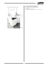
Idling ...................................................................LpA
84,4 dB (A)
Operating.............................................................LpA
95,7 dB (A)
The specified values are emission levels and are not necessarily to be seen
as safe operating levels. Although there is a correlation between emission
and imission levels, these do not constitute a basis for determining the ne-
cessity of additional safety measures. Workplace conditions which could
influence the noise imission level include the duration of resonance, spati-
al particulars, other noise sources etc. For example, the number of machi-
nes and other work being performed. The permissible workplace levels
can vary from country to country. This information is intended to allow
the user to make a better estimation of the hazards and risks involved.
3.3 Dust emission
The planer thicknesser has been dust emission inspected.
BPT-260S, BPT-310S:
At an air velocity of 20 m/s on the dust port dia 100mm:
Vacuum pressure
900 Pa
Volume flow
565 m³/h
BPT-410S:
At an air velocity of 20 m/s on the dust port dia 120mm:
Vacuum pressure
950 Pa
Volume flow
810 m³/h
The machine meets a workplace dust emission limit of 2 mg/m³.
3.4 Content of delivery
Planer thicknesser assembly
Jointer fence assembly.
Cutter block guard
Knife setting gauge
Operating tools
Operating manual
Spare parts list
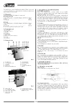
3.5 Machine description
Fig. 1
Fig. 2
Fig. 4
A Outfeed table
B Jointer fence
C ON/OFF switch
D Cutterblock guard
E Table tilt handle
F Table adjustment lock
G Table adjustment handle
H Infeed table
I Table-cabinet lock
J Mains plug
K Thickness table
L Power feed ON/OFF handle
M Thickness table lock
(BPT-310S, BPT-410S)
N Thickness table adjust
handwheel
O Dust hood
P Dust hood disengagement
knob
4. TRANSPORT AND START UP
4.1 Transport and installation
For transport use a forklift or hand trolley. Make sure the machine does
not tip or fall off during transport. Remove the carriage blots and slide the
machine carefully off the pallet.
ATTENTION:
The planer tables are precisely aligned ex. works. They
may only be loaded when they are closed and the tablecabinet locks (I, Fig
1) are engaged, otherwise they may be damaged. The machine is designed
to operate in closed rooms and must be placed stable on firm and levelled
ground. The machine can be bolted down if required.
4.2 Assembly
If you notice any transport damage while unpacking, notify your supplier
immediately. Do not operate the machine! Dispose of the packing in an
environmentally friendly manner. Clean all rust protected surfaces with a
mild solvent. Mount the table cutterblock guard (D, Fig 1).
Note:
The maximum clearance between cutter block guard and table may
not be more than 75mm
4.3 Mains connection
Mains connection and any extension cords used must comply with appli-
cable regulations. The mains voltage must comply with the information on
the machine licence plate. The mains connection must have a 16A surge-
proof fuse. Only use connection cables marked H07RN-F.
Connections and repairs to the electrical equipment may only be carried
out by qualified electricians.
ATTENTION:
- Check first if the cutter block runs freely and if all safety devices are fit-
ted before starting the machine.
- If the direction of rotation is not correct, the phase converter inside the
CCE Euro plug must be pushed in and turned 180°. (See rotation arrow on
machine for correct rotation)
4.4 Dust connection
Before initial operation, the machine must be connected to a dust extrac-
tor. The suction should switch on automatically when the jointer is swit-
ched on. The flow rate on the suction port must be 20m/sec. Flexible hoses
must be of nonflammable quality, and must be connected to the machine
ground system.
4.5 Starting operation
You can start the machine with the green on button. The red button on the
main switch stops the machine. The power feed can be engaged and disen-
gaged with handle (L, Fig 2). In case of machine overload the motor over-
load cut-off will react. After appr.10 min of cooling the machine can be
started again.
5. MACHINE OPERATION
Change of operating mode (planing to thicknessing and back) may on-
ly be performed when the machine is at a complete standstill.
5.1 Jointing and planing
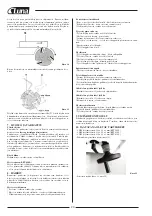
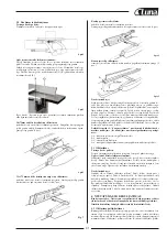
Correct operating position:
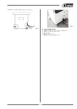
Position yourselves offset to the infeed table (Fig 4).
Work piece handling:
Feed the work piece straight across the infeed table, holding your fingers
close together, guiding the work piece with the palm of your hands. Never
put your hands under the cutter block cover. Always keep your hands well
clear of the cutter block Do not pull the work piece back over the unguar-
ded cutter block Always plane the work piece over its entire length. Adjust
depth of cut with lever (G). Loosen clamping knob (F) for adjustment.
Summary of Contents for 20841-0100
Page 59: ...58 2 3 0 V 4 0 0 V ...
Page 60: ...59 WIRING DIAGRAM BPT 310S ...
Page 61: ...60 WIRING DIAGRAM BPT 410S ...
Page 63: ...62 EXPLODED VIEW BPT 260S CUTTER BLOCK ASSEMBLY ...
Page 65: ...64 EXPLODED VIEW BPT 260S BASE ASSEMBLY ...
Page 67: ...66 EXPLODED VIEW BPT 260S INFEED TABLE ASSEMBLY ...
Page 69: ...68 EXPLODED VIEW BPT 260S DRIVE AND MOTOR ASSEMBLY ...
Page 71: ...70 EXPLODED VIEW BPT 260S THICKNESSING TABLE ASSEMBLY ...
Page 73: ...72 EXPLODED VIEW BPT 260S WORKING FENCE ASSEMBLY ...
Page 75: ...74 EXPLODED VIEW BPT 310S CUTTER BLOCK GUARD AND OUTFEED TABLE ASSEMBLY ...
Page 77: ...76 EXPLODED VIEW BPT 310S CUTTER BLOCK ASSEMBLY ...
Page 79: ...78 EXPLODED VIEW BPT 310S BASE ASSEMBLY ...
Page 82: ...81 EXPLODED VIEW BPT 310S DRIVE AND MOTOR ASSEMBLY ...
Page 84: ...EXPLODED VIEW BPT 310S THICKNESS TABLE ASSEMBLY 83 ...
Page 86: ...85 EXPLODED VIEW BPT 310S WORKING FENCE ASSEMBLY ...
Page 88: ...87 EXPLODED VIEW BPT 410S CUTTER BLOCK GUARD AND OUTFEED TABLE ASSEMBLY ...
Page 90: ...89 EXPLODED VIEW BPT 410S CUTTER BLOCK ASSEMBLY ...
Page 92: ...91 EXPLODED VIEW BPT 410S BASE ASSEMBLY ...
Page 95: ...94 EXPLODED VIEW BPT 410S DRIVE AND MOTOR ASSEMBLY ...
Page 97: ...96 EXPLODED VIEW BPT 410S THICKNESS TABLE ASSEMBLY ...
Page 99: ...98 EXPLODED VIEW BPT 410S WORKING FENCE ASSEMBLY ...
Page 103: ......
Page 104: ......
Page 105: ......
Page 106: ......


