Lucent Technologies Lineage
®
2000 100A Ferroresonant Rectifier J85503A-1
Issue 6 October 1998
List of Figures - 1
List of Figures
Figure 2-1: Location of Circuit Modules
Figure 2-2: CM1 Option Board Showing White Test
Clip Connection and Removable Straps K and M
Figure 2-3: CM2 Control Board Showing Test Clip
Connections and Other Component Details
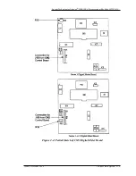
Figure 2-4: Partial Sketch of CM3 Digital Meter Board
Figure 2-5: Control Panel on the J85503A-1 Rectifier
Figure 2-6: Signal Flow between Rectifier and Lucent
Figure 5-1: Four Views of the J85503A-1 Rectifier
Figure 5-2: Front View of J85503A-1 Rectifier with Door
Figure 5-3: AC Input Components Mounted on the
Upper Left Side of the J85503A-1 Rectifier Behind
the Protective Shield
Figure 5-4: Output Polarity Conversion and
Component Detail on Bus Bar Assembly

