Lucent Technologies Lineage
®
2000 100A Ferroresonant Rectifier J85503A-1
5 - 18 Installation
Issue 6 October 1998
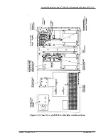
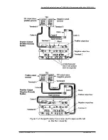
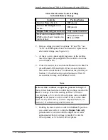
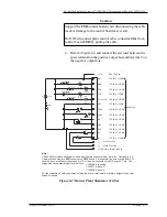
2. Remove straps provided for options “K” and “M,” not
“K,M” on CM1 option board and retain for replacement
after initial charge (see Figure 2-2).
3. At the ac service panel supplying power to the rectifier,
insert the input fuses assigned to the rectifier or turn the
circuit breaker On.
4. Close the rectifier door and turn the Power switch On. The
green Power LED must light. (If not, do not attempt to
turn on the circuit breaker. Troubleshoot the problem per
Section 7, Troubleshooting and Adjustments.) Wait 10
seconds after turning on the Power switch.
5. Holding the meter selector switch in the Rect V position,
use a small screwdriver to turn the Output Volts Adj
potentiometer clockwise until the digital meter reads
approximately battery voltage, typically 26 volts for
24-volt plants, or 52 volts for 48-volt plants.
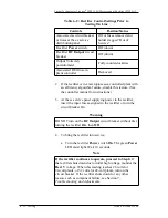
Table 5-D: Rectifier Control Settings
for Initial Battery Charge
Controls
Position/Status
Rectifier Power Switch
Off (down)
Rectifier DC Output circuit
breaker
Off (down)
Output Volts Adj potentiometer
Fully counterclockwise
Plant control connector J2A on
CM2 control board mounted on
inside of door
Disconnected from
P2A on CM2
Note
If the rectifier continues to operate, proceed to Step 5. If
the rectifier shuts down due to initial high voltage, monitor the
Rect V voltage. When this reading reaches 26 volts for
24-volt plants, or 52 volts for 48-volt plants, turn on the DC
Output circuit breaker on the rectifier. If the rectifier shuts
down for any other reason, such as component failure, see
Section 7, Troubleshooting and Adjustments.

