background image

User Manual of Network Camera 

29 


two-way audio, etc.


PTZ Control:   

Panning, tilting and zooming actions of the camera and the lighter and wiper control 

(if it supports PTZ function or an external pan/tilt unit has been installed).


Preset Setting/Calling:   

Set  and  call  the  preset  for  the  camera  (if  supports  PTZ  function  or  an  external 

pan/tilt unit has been installed).


5.2


Starting Live View 

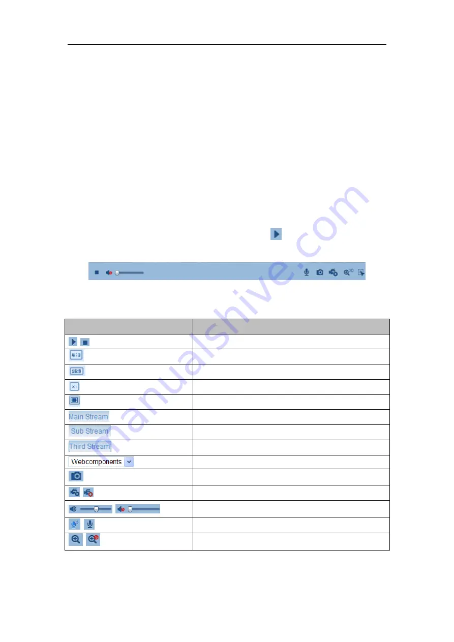
In the live view window as shown in Figure 5-2, click 


on the toolbar to start the 

live view of the camera.   


Figure 5-2


Live View Toolbar 

Table 5-1


Descriptions of the Toolbar 

Icon 

Description 

/


Start/Stop live view.


The window size is 4:3. 


The window size is 16:9. 


The original widow size. 


Self-adaptive window size. 


Live view with the main stream. 


Live view with the sub stream. 


Live view with the third stream. 


Click to select the third-party plug-in. 


Manually capture the picture.   

/


Manually start/stop recording. 


/


Audio on and adjust volume /Mute. 

/


Turn on/off microphone. 

/


Turn on/off 3D zooming function. 

Summary of Contents for CMIP7442W-28M

Page 1: ...Network Camera User Manual V5 2 0...

Page 2: ...e will readily improve or update the products or procedures described in the manual DISCLAIMER STATEMENT Underwriters Laboratories Inc UL has not tested the performance or reliability of the security...

Page 3: ...e received including interference that may cause undesired operation EU Conformity Statement This product and if applicable the supplied accessories too are marked with CE and comply therefore with th...

Page 4: ...1 and Limited Power Source standard If the product does not work properly please contact your dealer or the nearest service center Never attempt to disassemble the camera yourself We shall not assume...

Page 5: ...c radiation To avoid heat accumulation good ventilation is required for a proper operating environment Keep the camera away from water and any liquid While shipping the camera should be packed in its...

Page 6: ...tion in Manage and Ad hoc Modes 20 4 2 Easy Wi Fi Connection with WPS function 24 4 3 IP Property Settings for Wireless Network Connection 27 Chapter 5 Live View 28 5 1 Live View Page 28 5 2 Starting...

Page 7: ...ettings 64 6 5 3 Configuring Text Overlay Settings 66 6 5 4 Configuring Privacy Mask 67 6 6 Configuring and Handling Alarms 67 6 6 1 Configuring Motion Detection 68 6 6 2 Configuring Video Tampering A...

Page 8: ...mera 96 10 6 2 Restoring Default Settings 97 10 6 3 Exporting Importing Configuration File 97 10 6 4 Upgrading the System 98 10 7 RS 232 Settings 98 10 8 RS 485 Settings 99 Appendix 101 Appendix 1 SAD...

Page 9: ...003 Server 2008 32bits CPU Intel Pentium IV 3 0 GHz to Core i7 4000 series or higher depending on different video resolutions RAM 1G or higher Display 1024 768 resolution or higher Web Browser Interne...

Page 10: ...mera via a LAN you need to connect the network camera in the same subnet with your computer and install the SADP or NVMS7000 software to search and change the IP of the network camera Note For the det...

Page 11: ...2 3 Use the NVMS7000 PCNVR client software to list the online devices Please refer to the user manual of NVMS7000 PCNVR client software for detailed information 2 Change the IP address and subnet mas...

Page 12: ...camera to the WAN with a static IP or a dynamic IP 2 2 1 Static IP Connection Before you start Please apply a static IP from an ISP Internet Service Provider With the static IP address you can connec...

Page 13: ...t the network camera through a web browser or the client software over the internet Figure 2 4 Accessing the Camera through Router with Static IP Connecting the network camera with static IP directly...

Page 14: ...tting interface of the router 7 Visit the camera via the applied domain name Connecting the network camera via a modem Purpose This camera supports the PPPoE auto dial up function The camera gets a pu...

Page 15: ...Settings for detailed configuration 3 Visit the camera via the applied domain name Private Domain Name Resolution Figure 2 8 Private Domain Name Resolution Steps 1 Install and run the IP Server softw...

Page 16: ...assword and click Login Figure 3 1 Login Interface Notes The default user name is admin and the default password is 12345 Multi language is supported English Simplified Chinese Traditional Chinese Rus...

Page 17: ...ure 3 2 Download and Install Plug in Figure 3 3 Install Plug in 1 Figure 3 4 Install Plug in 2 Note You may have to close the web browser to install the plug in Please reopen the web browser and log i...

Page 18: ...PCNVR The product CD contains the NVMS7000 PCNVR You can view the live video and manage the camera with the software Follow the installation prompts to install the software The control panel and live...

Page 19: ...User Manual of Network Camera 19 Figure 3 6 NVMS7000 Live View Note For detailed information about the software please refer to the user manual of the NVMS7000 PCNVR...

Page 20: ...the cameras with the built in Wi Fi module 4 1 Configuring Wi Fi Connection in Manage and Ad hoc Modes Before you start A wireless network must be configured Wireless Connection in Manage Mode Steps...

Page 21: ...network connection you set on the router Wireless Connection in Ad hoc Mode If you choose the Ad hoc mode you don t need to connect the wireless camera via a router The scenario is the same as you con...

Page 22: ...hoc Connection Point 6 Choose the SSID and connect Security Mode Description Figure 4 6 Security Mode You can choose the Security Mode as not encrypted WEP WPA personal WPA enterprise WPA2 personal an...

Page 23: ...own as 40 64 and 104 128 Key type The key types available depend on the access point being used The following options are available HEX Allows you to manually enter the hex key ASCII In this method th...

Page 24: ...to present to the network Password Enter the password of the network PEAP Version Select the PEAP version used at the access point Label Select the label used by the access point EAPOL version Select...

Page 25: ...Settings WPS PBC Mode PBC refers to the Push Button Configuration in which the user simply has to push a button either an actual or virtual one as the button on the configuration interface of the IE...

Page 26: ...k is connected automatically PIN Mode The PIN mode requires a Personal Identification Number PIN to be read from either a sticker or the display on the new wireless device This PIN must then be entere...

Page 27: ...ss network interface controller is 192 168 1 64 When you connect the wireless network you can change the default IP Steps 1 Enter the TCP IP configuration interface Configuration Advanced Configuratio...

Page 28: ...o enter Live View Playback Log and Configuration page respectively Display Control Click each tab to adjust the layout and the stream type of the live view And you can click the drop down to select th...

Page 29: ...the live view window as shown in Figure 5 2 click on the toolbar to start the live view of the camera Figure 5 2 Live View Toolbar Table 5 1 Descriptions of the Toolbar Icon Description Start Stop li...

Page 30: ...PTZ Control Purpose In the live view interface you can use the PTZ control buttons to realize pan tilt zoom control of the camera Before you start To realize PTZ control the camera connected to the n...

Page 31: ...rol Panel Icon Description Zoom in out Focus near far Iris Light on off Wiper on off One touch focus Initialize lens Adjust speed of pan tilt movements 5 4 2 Setting Calling a Preset Setting a Preset...

Page 32: ...ct a defined preset from the list and click to call the preset Or you can place the mouse on the presets interface and call the preset by typing the preset No to call the corresponding presets Figure...

Page 33: ...User Manual of Network Camera 33 Figure 5 6 Add Patrol Path 6 Click to save a patrol 7 Click to start the patrol and click to stop it Optional Click to delete a patrol...

Page 34: ...record and captured using the web browser and thus the saving paths of them are on the PC running the browser Steps 1 Enter the Local Configuration interface Configuration Local Configuration Figure...

Page 35: ...when a face is detected it will be marked with a green rectangle on the live view Image Format Choose the image format for picture capture Record File Settings Set the saving path of the recorded vid...

Page 36: ...tion to configure the time synchronization and DST settings Steps 1 Enter the Time Settings interface Configuration Basic Configuration System Time Settings Or Configuration Advanced Configuration Sys...

Page 37: ...ra is set in a customized network NTP software can be used to establish a NTP server for time synchronization Synchronizing Time Synchronization Manually Enable the Manual Time Sync function and then...

Page 38: ...ously without conflicting to each other and at least one IP version should be configured Steps 1 Enter TCP IP Settings interface Configuration Basic Configuration Network TCP IP Or Configuration Advan...

Page 39: ...port No of the camera e g HTTP port RTSP port and HTTPS port Steps 1 Enter the Port Settings interface Configuration Basic Configuration Network Port Or Configuration Advanced Configuration Network P...

Page 40: ...er Name and Password should be assigned by your ISP 4 Click Save to save and exit the interface Note A reboot is required for the settings to take effect 6 3 4 Configuring DDNS Settings Purpose If you...

Page 41: ...ble HiDDNS IPServer and DynDNS DynDNS Steps 1 Enter Server Address of DynDNS e g members dyndns org 2 In the Domain text field enter the domain name obtained from the DynDNS website 3 Enter the Port o...

Page 42: ...IP address of the computer that runs the IP Server software Figure 6 11 IP Server Settings Note For the US and Canada area you can enter 173 200 91 74 as the server address NO IP Steps 1 Choose the D...

Page 43: ...The domain is the same with the device alias in the HiDDNS server 4 Click Save to save the new settings Note A reboot is required for the settings to take effect LTS Steps 1 Enter the Server Address...

Page 44: ...SNMP port By setting the Trap Address the camera can send the alarm event and exception messages to the surveillance center Note The SNMP version you select should be the same as that of the SNMP sof...

Page 45: ...ame as the settings you configure here 4 Click Save to save and finish the settings Note A reboot is required for the settings to take effect 6 3 6 Configuring 802 1X Settings Purpose The IEEE 802 1X...

Page 46: ...Configure the 802 1X settings including EAPOL version user name and password Note The EAPOL version must be identical with that of the router or the switch 4 Enter the user name and password to acces...

Page 47: ...DSCP value is used in the IP header to indicate the priority of the data 3 Click Save to save the settings Note A reboot is required for the settings to take effect 6 3 8 Configuring FTP Settings Pur...

Page 48: ...function must be supported by the FTP server 3 Click Save to save the settings Note If you want to upload the captured pictures to FTP server you have to enable the continuous snapshot or event trigge...

Page 49: ...erver settings under Basic Configuration Network TCP IP or Advanced Configuration Network TCP IP before using the Email function Steps 1 Enter the TCP IP Settings Configuration Basic Configuration Net...

Page 50: ...P port for SMTP is 25 not secured And the SSL SMTP port is 465 Enable SSL Check the checkbox to enable SSL if it is required by the SMTP server Attached Image Check the checkbox of Attached Image if y...

Page 51: ...NAT settings interface Configuration Advanced Configuration Network NAT 2 Choose the port mapping mode To port mapping with the default port numbers Choose Port Mapping Mode To port mapping with the...

Page 52: ...entication of the web site and associated web server that one is communicating with which protects against Man in the middle attacks Perform the following steps to set the port number of https E g If...

Page 53: ...TTPS Settings Create the self signed certificate 1 Click Create button to enter the creation interface Figure 6 24 Create Self signed Certificate 2 Enter the country host name IP validity and other in...

Page 54: ...or signature 3 After receiving the signed valid certificate import the certificate to the device 3 There will be the certificate information after you successfully create and install the certificate F...

Page 55: ...m Video Type Select the stream type to video stream or video audio composite stream The audio signal will be recorded only when the Video Type is Video Audio Resolution Select the resolution of the vi...

Page 56: ...pported video encoding may differ according to the different platform Profile Basic profile Main Profile and High Profile for coding are selectable I Frame Interval Set the I Frame interval to 1 400 S...

Page 57: ...en you set the function on the noise detected can be filtered 3 Click Save to save the settings 6 4 3 Configuring ROI Encoding ROI stands for the region of interest And the ROI encoding enables you to...

Page 58: ...mic tracking The fixed region encoding is the ROI encoding for the manually configured area And you can choose the Image Quality Enhancing level for ROI encoding and you can also name the ROI area The...

Page 59: ...saturation hue sharpness etc Note The display parameters vary according to the different camera model Please refer to the actual interface for details Steps 1 Enter the Display Settings interface Conf...

Page 60: ...contrast of the image which ranges from 1 100 and the default value is 50 Exposure Settings If the camera is equipped with the fixed lens only Manual is selectable and the iris mode is not configurab...

Page 61: ...t night mode Auto the camera switches between the day mode and the night mode according to the illumination automatically The sensitivity ranges from 0 7 the higher the value is the easier the mode sw...

Page 62: ...e dark area of the scene HLC High Light Compression function can be used when there are strong lights in the scene affecting the image quality White Balance White balance is the white rendition functi...

Page 63: ...the needless information such as the wall and get more meaningful information of the scene Scene Mode Choose the scene as indoor or outdoor according to the real environment Video Standard 50 Hz and...

Page 64: ...detailed information of each parameter please refers to day night auto switch session 3 Click Day tab to configure the parameters applicable for day mode 4 Click Night tab to configure the parameters...

Page 65: ...text field of Camera Name 4 Select from the drop down list to set the time format date format display mode and the OSD font size 5 Define the font color of the OSD by clicking the drop down and black...

Page 66: ...ext overlay Steps 1 Enter the Text Overlay Settings interface Configuration Advanced Configuration Image Text Overlay Figure 6 37 Text Overlay 2 Check the checkbox in front of textbox to enable the on...

Page 67: ...sk to enable this function 3 Click Draw Area Figure 6 38 Privacy Mask Settings 4 Click and drag the mouse in the live video window to draw the mask area Note You are allowed to draw up to 4 areas on t...

Page 68: ...tion detection detects the moving objects in the configured surveillance area and triggers the certain action as a respond to detection In order to detect the moving objects accurately and reduce the...

Page 69: ...area 5 Click Stop Drawing to finish drawing one area 6 Optional Click Clear All to clear all of the areas 7 Optional Move the slider to set the sensitivity of the detection 2 Set the Arming Schedule...

Page 70: ...rm Actions for Motion Detection Check the checkbox to select the linkage method Notify surveillance center send email upload to FTP trigger channel and trigger alarm output are selectable You can spec...

Page 71: ...nformation Trigger Channel The video will be recorded when the motion is detected You have to set the recording schedule to realize this function Please refer to Section 7 2 for detailed information T...

Page 72: ...save the settings Day Night Auto Switch Steps 1 Draw the detection area as in the normal configuration mode Up to 8 areas are supported 2 Select Auto Switch for Switch Day and Night Settings Figure 6...

Page 73: ...he sensitivity and proportion of object on the area for the selected area in the daytime 6 Slide the cursor to adjust the sensitivity and proportion of object on the area for the selected area at nigh...

Page 74: ...otion detection Refer to Task 2 Set the Arming Schedule for Motion Detection in Section 6 6 1 5 Check the checkbox to select the linkage method taken for the video tampering Audible warning notify sur...

Page 75: ...o Task 3 Set the Alarm Actions for Motion Detection in Section 6 6 1 5 You can also choose the PTZ linking for the alarm input if your camera is installed with a pan tilt unit Check the relative check...

Page 76: ...ngs of the arming schedule for motion detection Refer to Task 2 Set the Arming Schedule for Motion Detection in Section 6 6 1 5 You can copy the settings to other alarm outputs 6 Click Save to save th...

Page 77: ...cts crossing a pre defined area The line crossing direction can be set as bidirectional from left to right or from right to left And a series of linkage method will be triggered if any object is detec...

Page 78: ...n be detected 4 Set the sensitivity 1 100 5 Choose another line crossing on the dropdown list to configure Up to 4 line crossing areas are configurable 6 Click Save to save the settings 6 6 7 Configur...

Page 79: ...efines the size of the object which can trigger the alarm when the sensitivity is high a very small object can trigger the alarm Percentage Range 1 100 Percentage defines the ratio of the in region pa...

Page 80: ...e recorded files log files etc Steps 1 Add the network disk 1 Enter the NAS Network Attached Storage Settings interface Configuration Advanced Configuration Storage NAS Figure 7 1 Add Network Disk 2 E...

Page 81: ...sk is Uninitialized check the corresponding checkbox to select the disk and click Format to start initializing the disk When the initialization completed the status of disk will become Normal Figure 7...

Page 82: ...of scheduled recording are stored in the SD card if supported or in the network disk Steps 1 Enter the Record Schedule Settings interface Configuration Advanced Configuration Storage Record Schedule...

Page 83: ...rations vary depending on the camera model 4 Click Edit to edit the record schedule Figure 7 7 Record Schedule 5 Choose the day to set the record schedule 1 Set all day record or segment record If you...

Page 84: ...e recorded when the alarm is triggered via the external alarm input channels Besides configuring the recording schedule you have to set the Alarm Type and check the checkbox of Trigger Channel in the...

Page 85: ...es before the date and click Copy 4 Click OK to save the settings and exit the Edit Record Schedule interface 6 Click Save to save the settings 7 3 Configuring Snapshot Settings Purpose You can config...

Page 86: ...and check Upload Picture checkbox in FTP Settings interface Please refer to Section 6 3 8 Configuring FTP Settings for more details to configure FTP parameters 2 Check the Enable Timing Snapshot chec...

Page 87: ...User Manual of Network Camera 87 Figure 7 9 Snapshot Settings...

Page 88: ...work disks or SD cards Steps 1 Click Playback on the menu bar to enter playback interface Figure 8 1 Playback Interface 2 Select the date and click Search Figure 8 2 Search Video 3 Click to play the v...

Page 89: ...e the file paths locally for downloaded playback video files and pictures in Local Configuration interface Please refer to Section 6 1 for details Drag the progress bar with the mouse to locate the ex...

Page 90: ...camera or insert a SD card in the camera Steps 1 Click Log on the menu bar to enter log searching interface Figure 9 1 Log Searching Interface 2 Set the log search conditions to specify the search in...

Page 91: ...accounts Up to 15 user accounts can be created Figure 10 1 User Information Add a User Steps 1 Click Add to add a user 2 Input the new User Name select Level and input Password Note The level indicate...

Page 92: ...y the User Name Level or Password 3 In the Basic Permission field and Camera Configuration field you can check or uncheck the permissions 4 Click OK to finish the user modification Figure 10 3 Modify...

Page 93: ...on type basic or disable in the drop down list to enable or disable the RTSP authentication Note If you disable the RTSP authentication anyone can access the video stream by the RTSP protocol via the...

Page 94: ...n Anonymous Checkbox 4 Check the checkbox of Anonymous and click Login Note Only live view is available for the anonymous user 10 4IP Address Filter Purpose This function makes it possible for access...

Page 95: ...ddress Steps 1 Left click an IP address from filter list and click Modify 2 Modify the IP address in the text filed Figure 10 9 Modify an IP 3 Click the OK to finish modifying Delete an IP Address Lef...

Page 96: ...ersion Number of Channels Number of HDDs Number of Alarm Input and Number of Alarm Output are displayed The information cannot be changed in this menu It is the reference for maintenance or modificati...

Page 97: ...File Purpose Configuration file is used for the batch configuration of the camera which can simplify the configuration steps when there are a lot of cameras needing configuring Steps Enter the Mainte...

Page 98: ...o start remote upgrade Note The upgrading process will take 1 to 10 minutes Please don t disconnect power of the camera during the process The camera reboots automatically after upgrading Figure 10 14...

Page 99: ...Settings Note If you want to connect the camera by the RS 232 port the parameters of the RS 232 should be exactly the same with the parameters you configured here 2 Click Save to save the settings 10...

Page 100: ...click Save to save the settings By default the Baud Rate is set as 9600 bps the Data Bit is 8 the stop bit is 1 and the Parity and Flow Control is None Note The Baud Rate PTZ Protocol and PTZ Address...

Page 101: ...ive devices online Search online devices automatically After launch the SADP software it automatically searches the online devices every 15 seconds from the subnet where your computer locates It displ...

Page 102: ...e right side or click to show the network parameter panel Modify network parameters Steps 1 Select the device to be modified in the device list and the network parameters of the device will be display...

Page 103: ...our technical engineers to get the serial code Note Serial code is a series of characters combined by the start time and the serial number of the device 2 Input the code in the Serial code field and c...

Page 104: ...the LAN parameters of the router as in the following figure including IP address and subnet mask settings Figure A 2 2 Set the LAN parameters 3 Set the port mapping in the virtual severs of Forwarding...

Page 105: ...he network camera at 192 168 1 23 2 Map the port 81 8001 555 and 8201 for the network camera at 192 168 1 24 3 Enable ALL or TCP protocols 4 Check the Enable checkbox and click Save Figure A 2 3 Port...

Reviews: