background image


Keep the camera away from liquid while in use for 

non-water-proof device. 


While in delivery, the camera shall be packed in its 

original packing, or packing of the same texture. 

 
Mark Description 

Table 0-1 Mark Description 

Mark 

Description 


DC Voltage 


1


Introduction 

1.1


Product Features 

The main features are as follows: 


High performance CMOS sensor 


OSD menu with configurable parameters 


Smart IR 


3-Axis Adjustment 

1.2


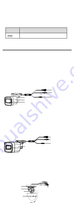
Overview 

1.2.1


Overview of Type I Camera 

Switch Button

Power Cord

Video Cable

Bracket
Main Body
Lens


Figure 1-1


Overview of Type I Camera 

Note: 

Press and hold the switch button for 5 seconds to 
switch the video output. Four kinds of video outputs 
are available: TVI, AHD, CVI, and CVBS. 

1.2.2


Overview of Type II Camera 

Power Cord

Video Cable

Switch Button

Bracket

Main Body

Lens


Figure 1-2


Overview of Type II Camera 

Note: 

Press and hold the switch button for 5 seconds to 

switch the video output. Four kinds of video outputs 
are available: TVI, AHD, CVI, and CVBS. 

1.2.3


Overview of Type III Camera 

Video Cable

Power Cord

Switch Button

Mounting Base

Pan Position 

Bracket

Tilt Position Bracket

IR Light

Lens

Bubble

Safety Rope


Figure 1-3


Overview of Type III Camera 

Summary of Contents for 5MP Series

Page 1: ...or requests do not hesitate to contact the dealer This manual may contain several technical mistakes or printing errors and the content is subject to change without notice The updates will be added t...

Page 2: ...se undesired operation EU Conformity Statement This product and if applicable the supplied accessories too are marked with CE and comply therefore with the applicable harmonized European standards lis...

Page 3: ...mounting is adopted If smoke odor or noise rise from the device turn off the power at once and unplug the power cord and then contact the service center Never attempt to disassemble the camera by unpr...

Page 4: ...o Cable Bracket Main Body Lens Figure 1 1 Overview of Type I Camera Note Press and hold the switch button for 5 seconds to switch the video output Four kinds of video outputs are available TVI AHD CVI...

Page 5: ...VI AHD CVI and CVBS 1 2 4 Overview of Type IV Camera Black Liner Bubble Adjusting Screws Switch Button Power Cord Video Cable IR Zoom module Figure 1 4 Overview of Type III Camera Note Press and hold...

Page 6: ...1 Ceiling Wall Mounting of Type I Camera Before you start The ceiling mounting and the wall mounting are similar Following takes ceiling mounting as an example Steps 1 Paste the drill template supplie...

Page 7: ...in the center of the drill template when adopting ceiling outlet to route the cable 3 Route cables through the cable hole or the side opening 4 Attach the camera to the ceiling with supplied screws F...

Page 8: ...screw holes and cable hole optional on the ceiling according to the drill template Drill Template Hole A for cables routed through the ceiling screw hole 1 for MountingBase 1 1 1 A 120 Figure 2 7 Dri...

Page 9: ...Rotation Position 0 to 355 Tilt Position 0 to 75 Tilt Adjusting Screw Figure 2 10 3 Axis Adjustment 8 Install the bubble back and tighten screws to finish the installation Figure 2 11 Install the Bub...

Page 10: ...ing ceiling outlet to route the cable 5 Route the cables through the cable hole optional or the side opening 6 Attach the mounting base to the ceiling and secure it with PA4 25 screws Figure 2 15 Atta...

Page 11: ...nd down to adjust the tilt position 0 to 70 3 Rotate the camera body to adjust the rotation position 0 to 350 9 Put the black liner and bubble back to finish the installation Figure 2 17 Put the Black...

Page 12: ...on the monitor 3 Click PTZ Control to enter the PTZ Control interface 4 Call the camera menu by clicking button or call preset No 95 MAIN MENU VIDEO SETTINGS FACTORY DEFAULT EXIT EXPOSURE MODE CONTRA...

Page 13: ...where the light is strong HLC Highlight Compensation HLC stands for highlight compensation The camera detects the strong spots the over exposure portion of image then reduce the brightness of the str...

Page 14: ...s You can turn on off the IR LIGHT and set the value of SMART IR in this menu DAY NIGHT MODE IR LIGHT SMART IR D N THRESHOLD N D THRESHOLD BACK EXIT SAVE EXIT AUTO ON 2 5 5 Figure 3 5 AUTO IR LIGHT Yo...

Page 15: ...ust the color temperature according to the environment It can remove unrealistic color casts in the image You can set the mode to AUTO or MANUAL AUTO Under AUTO mode white balance is being adjusted au...

Page 16: ...light conditions and delivering more accurate and sharp image MIRROR OFF H V and HV are selectable for mirror OFF The mirror function is disabled H The image flips 180 horizontally V The image flips...

Reviews: