4-4
Register Descriptions
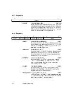
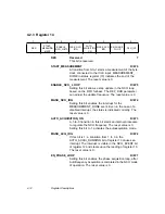
4.1.1 Register 0
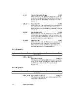
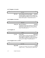
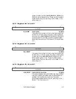
FCOEFF
Filter Coefficient Shift
R/W [7:0]
Writing to this location shifts the 196-byte filter coefficient
shift register forward by one and puts this entry at the end
of the queue. Reading this location shows the last entry
of the coefficient shift register without shifting it. The reset
values for the bit fields in this register are 0.
4.1.2 Register 1
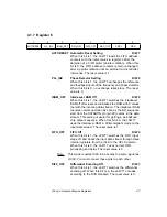
SERIN
Serial/Parallel Input Setting
R/W 7
When this bit is 1, the L64777 uses DIN[0] as serial input
and considers ICLK as a bit clock. When this bit is 0, the
L64777 uses DIN[7:0] as parallel input and ICLK as a
byte clock. The reset value is 0.
NEWSYNC
NEWSYNC Insertion
R/W 6
When this bit is 1, the L64777 inserts a new sync word
(NEWSYNC, see Section 2.6.1) into the data stream.
When this bit is 0, the L64777 leaves the data stream
unchanged. The reset value is 1.
EXTSYNC
Synchronization Setting
R/W 5
When this bit is 1, the L64777 synchronizes positive
pulses on the FSTARTIN pin. When this bit is 0, the
L64777 synchronizes on SYNC_BYTE in the input
stream. The reset value is 0.
PLLSET
PLL Divider Setting
R/W 4
When this bit is 1, the L64777 forces a load of PLL
dividers. When this bit is 0, the L64777 runs the PLL
dividers normally. The reset value is 0.
FREQ_PHASE Frequency/Phase Compare
R/W 3
When this bit is 1, the L64777 uses frequency compare
for external VCO control. When this bit is 0, the L64777
uses phase compare. The reset value is 1.
7
0
FCOEFF
7
6
5
4
3
2
0
SERIN
NEWSYNC
EXTSYNC
PLLSET
FREQ_PHASE
MSIZE
Summary of Contents for L64777
Page 1: ...L64777 DVB QAM Modulator Order Number I14031 A Technical Manual June 2000...
Page 10: ...x Contents...
Page 14: ...1 4 Introduction...
Page 90: ...5 10 Signals...
Page 110: ...A 8 Programming the L64777 in Serial Host Interface Mode...
Page 116: ...C 2 Monitoring Device Internal Signals...
Page 124: ......

