2-26
Modulator Architecture
2.10 Differential Encoder and QAM Mapping
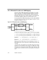
This block performs differential encoding and mapping for 16 and 64
QAM, as specified in the
Digital Broadcasting Systems for Television
Sound and Data Services: Framing Structure, Channel Coding and
Modulation Cable Systems, the baseline document, and its extensions.
The QAM 256 mapping is taken from the DVB document 1190.
The encoder performs differential encoding on the two most significant
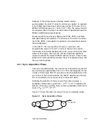
bits of each symbol, as shown in the block diagram in Figure 2.18 and
specified in equations 2.1 and 2.2.
Figure 2.18 Differential Encoder and QAM Mapping
To clarify the underlying concepts in Figure 2.18, here are two examples:
1.
If m = 4, A
k
is bit 3, B
k
is bit 2, and the LSB = (m
−
2) bits = bits [1:0].
2.
If m = 6, A
k
is bit 5, B
k
is bit 4, and the LSB = (m
−
2) bits = bits [3:0].
Equation 2.1
Equation 2.2
Mapping performs a table look-up for the concatenation of the (m
−
2)
least significant bits of each symbol with the differentially generated bits
I
k
and Q
k
.
In 64 QAM mode, the mapping block of the differential encoder maps the
6-tuples to two 3-bit values for I and Q output. In 16 QAM mode, it maps
the 4-tuples to two 2-bit values. For lower QAM modes, it aligns the I and
Q output values to the MSB and stuffs the least-significant bit (LSB) with
ones.
8
Byte to
Differential
Encoder
Mapping
MSB = A
k
B
k
I
k
Q
k
I[3:0]
Q[3:0]
M-tuple
From
Interleaver
MSB
−
1
LSB
m
−
2
I
k
A
k
B
k
⊕
(
)
¬
(
)
A
k
I
k
1
–
⊕
(
)
A
k
B
k
⊕
(
)
A
k
Q
k
1
–
⊕
(
)
+
=
Q
k
A
k
B
k
⊕
(
)
¬
(
)
B
k
Q
k
1
–
⊕
(
)
A
k
B
k
⊕
(
)
B
k
I
k
1
–
⊕
(
)
+
=
Summary of Contents for L64777
Page 1: ...L64777 DVB QAM Modulator Order Number I14031 A Technical Manual June 2000...
Page 10: ...x Contents...
Page 14: ...1 4 Introduction...
Page 90: ...5 10 Signals...
Page 110: ...A 8 Programming the L64777 in Serial Host Interface Mode...
Page 116: ...C 2 Monitoring Device Internal Signals...
Page 124: ......


