Connecting the L64777 to the LSI Logic L64724
B-3
B.3 Connecting the L64777 to the LSI Logic L64724
The L64777 can be connected to the satellite receiver device L64724.
The L64724 uses an interpolation-based digital receiver. Thus, it outputs
a transport-rate byte clock with the granularity of the L64724 internal
processing clock, PCLK. See the LSI Logic
L64724 Satellite Receiver
Technical Manual (April 2000).
A digital NCO generates this byte clock, which consists of clock cycles
having a length of k or k + 1 PCLK cycles. Usually, the rate of the byte
clock is exactly that of the received transport stream rate.
To ease interfacing, the L64724 supports two modes of byte-clock
generation. Mode 2 of the synchronous parallel interface (SPI) is best
suited for interconnection with L64777. In this mode, the L64724 outputs
204-byte clock cycles, together with an indication for the 188 valid data
bytes. Connect the byte clock to the ICLK input of the L64777, as a
reference for generating the output sampling rate (OCLK); and connect
the PCLK output of the L64724 to the PCLK input of L64777.
To keep the loop bandwidth as low as possible, L64777 provides a digital
interpolation scheme and an NCO to lock to the byte clock in PLL mode 2.
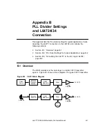
Figure B.2 provides a simplified illustration of the signals between the
L64724 and the L64777.
Figure B.2
Signals between the L64724 and L64777
L64724
L64777
PCLK
PCLK
DIN(7:0)
DVALIDIN
ICLK
CO(7:0)
DVALIDOUT
BCLKOUT
Summary of Contents for L64777
Page 1: ...L64777 DVB QAM Modulator Order Number I14031 A Technical Manual June 2000...
Page 10: ...x Contents...
Page 14: ...1 4 Introduction...
Page 90: ...5 10 Signals...
Page 110: ...A 8 Programming the L64777 in Serial Host Interface Mode...
Page 116: ...C 2 Monitoring Device Internal Signals...
Page 124: ......

