10
GIPAM User Manual
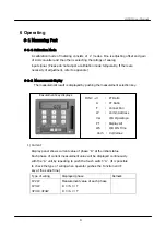
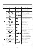
2) Voltage
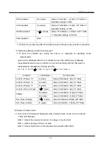
Each phase of voltage measurement value will be displayed continuously with the
“
V
”
unit by repeating to push the touch switch
“
V
”
.
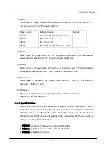
Type of wiring
Displayed phase
Remark
1P2W
1P3W
3P3W
3P4W
Measurement value of each phase
RN → TN → RT
RS → ST → RT
RN → SN → TN →RS → ST → RT
3) Power
Active power is displayed with
“
W
”
unit by pushing touch switch
“
W
”
and reactive
power will be displayed with
“
Var
”
by pushing touch switch Var.
4) Energy
Active energy is displayed with
“
WH
”
unit by pushing touch switch
“
Wh
”
and reactive
energy will be displayed with unit
“
Varh
”
pushing touch switch Varh.
5) Power Factor
Power factor is displayed by pushing touch switch PF with
“
%
”
unit and also
displayed
“
LEAD
”
or
“
LAG
”
.
6) Frequency
Frequency is displayed by pushing touch switch F with
“
Hz
”
unit and it
displays the first decimal place.
6-1-3 Special Function
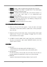
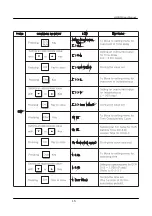
Pushing the FUNC Switch, it is transferred to special function mode and the switch
lamp is turned on. It shows special function mode continuously during the switch lamp
of FUNC Switch is on. If operator pushes the FUNC Switch again, it will return to
standard mode. If it is changed to special mode, measuring switch function will be
changed and it displays as followings:
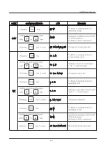
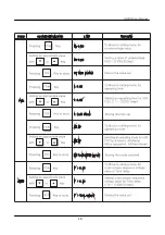
1) FUNC+V: It displays PT ratio setting value of DIP Switch.
2) FUNC+A: It displays CT ratio setting value of DIP Switch.
3) FUNC+A: It displays wiring type
Summary of Contents for GIMAC-II
Page 2: ...GIPAM USER MANUAL Digital Integrated Protection Monitoring Equipment GIPAM User Manual...
Page 16: ...15 GIPAM User Manual...
Page 17: ...16 GIPAM User Manual...
Page 18: ...17 GIPAM User Manual...
Page 19: ...18 GIPAM User Manual...
Page 20: ...19 GIPAM User Manual...
Page 21: ...20 GIPAM User Manual...
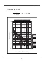
Page 25: ...24 GIPAM User Manual 2 VI Very Inverse Time OCR OCGR t TL TL 0 05 1 00 13 5 I Is 1...
Page 26: ...25 GIPAM User Manual 3 EI Extremely Inverse Time OCR OCGR t TL TL 0 05 1 00 80 I Is 2 1...
Page 27: ...26 GIPAM User Manual 4 LI Long Inverse Time OCR OCGR t TL TL 0 05 1 00 120 I Is 1...
Page 33: ...32 GIPAM User Manual 4 Three Phase Three Wire System with 3 CTs with 3PTs...
Page 36: ...35 GIPAM User Manual 3 Terminal Block 7 7 External Dimension mm...
Page 44: ...GIMAC II USER MANUAL Digital Integrated Metering Control Equipment GIMAC II User Manual...
Page 53: ...10 A57 IgYf AUbiU 5 2 Wiring...
Page 54: ...11 A57 IgYf AUbiU 1 3P4W 3 CT 2 3P3W 3CT With 3PTs...
Page 55: ...12 A57 IgYf AUbiU 3 3P3W 2CT 4 1P3W...
Page 56: ...13 A57 IgYf AUbiU 5 1P2W 6 Odering Information...
Page 57: ...GMPC III USER MANUAL Protocol converter III GMPC III User Manual...

