


I456
GB
CS
01
18
13
G
B
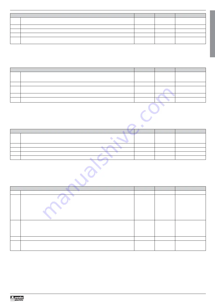
P05 - MISCELLANEOUS UoM Default Range
P05.01
Torque control OFF ON
OFF
P05.02
Torque linearization coefficient 100 50…150%
P05.03
Maximum torque limit OFF OFF / 10…200%Tn
P05.04
Delay to start sec 0 0.0…20.0
P05.05
Main RS485 function SLAVE SLAVE
REM EXP
P05.01
– Determines whether the acceleration and deceleration ramps have to be run under torque control or voltage control.
P05.02
– Due to the various construction standards (IE2, IE3, etc.), motors may have a different torque delivery than envisaged. In such cases, is useful to modify this parameter to optimise the torque delivery.
Values greater than 100% are set when the acceleration is smooth during the initial stage and abrupt at the end. Vice-versa, values lower than 100% are set when acceleration is abrupt at the start and
gradual at the end.
P05.03
– Limits the maximum torque during acceleration. This is used when, due to large inertial masses, there may be transmission problems such as slipping belts or failure of mechanical parts.
P05.05
– Defines the operation of the optional RS-485 interface.
SLAVE
= Normal operation as a Modbus slave.
REM EXP
= control by an external expansion unit.
P06 – PROGRAMMABLE INPUTS (INPn, n=1…3) UoM Default Range
P06.n.01
INPn input function INP1=START (see Programmable
INP2 =STOP (NC) input functions table)
INP3=OFF
P06.n.02
Channel nr. (x) OFF OFF / 1…99
P06.n.03
Contact type NO NO
NC
P06.n.04
Closing delay sec 0.05 0.00-600.00
P06.n.05
Opening delay sec 0.05 0.00-600.00
Note: This menu is divided into 3 sections for each programmable digital input INP1..INP3.
P06.n.01
– Selects the function of the input in question (see Programmable input function table).
P06.n.02
– Index possibly associated to the function programmed under the previous parameter. Example: If the input function is set to Commands menu execution Cxx and this input must execute the command
C.07, then P06.n.02 must be set to value 7.
P06.n.03
– Contact type selection: NO = normally open or NC = normally closed.
P06.n.04
– Delay on the closing of the selected input contact.
P06.n.05
– Delay on the opening of the selected input contact.
P07 – PROGRAMMABLE OUTPUTS (OUTn, n=1..3) UoM Default Range
P07.n.01
Output function OUT1=GLB. ALA (see Programmable
OUT2=LIN.CONT output functions table)
OUT3=RUN
P07.n.02
Channel nr. (x) 1 1 - 8
P07.n.03
Normal status NOR NOR-REV
P07.n.04
Delay ON sec 0 0.0-6000.0
P07.n.05
Delay OFF sec 0 0.0-6000.0
Note: This menu is divided into 3 sections, referred to digital outputs OUT1…OUT3.
P07.n.01
– Selects the function of the output (see Programmable output function table ).
P07.n.02
– Index possibly associated to the function programmed under the previous parameter. Example: If the function of the output is set to the Alarm Axx function and this output must be energised when alarm
A16 occurs, then P07.n.02 must be set to value 16.
P07.n.03
– This parameter sets the output status when the associated function is not active:
NOR
= de-energised output,
REV
= energised output.
P07.n.04
– Defines the output energisation delay.
P07.n.05
– Defines the output de-energisation delay.
P08 – COMMUNICATION (COMn, n=1..1) UoM Default Range
P08.n.01
Serial node address 01 01-255
P08.n.02
Baudrate bps 9600 1200
2400
4800
9600
19200
38400
57600
115200
P08.n.03
Data format 8 BIT – N 8BIT – N
8BIT – O
8BIT – E
7BIT – O
7BIT - E
P08.n.04
Stop bits 1 1-2
P08.n.05
Protocol MOD RTU MOD RTU
MOD ASCII
MOD TCP
P08.n.01
– Serial address (node) of the soft starter.
P08.n.02
– Communication port transmission speed.
P08.n.03
– Data format. 7 bit setting is available for ASCII protocol only.
P08.n.04
– Stop bit number.
P08.n.05
– Communication protocol selection (Modbus RTU, Modbus ASCII or Modbus TCP).


