background image


  Code: MSGB202$0500.doc                                       18/06/2004                                                                       P.  17 / 20


Parameters menu 

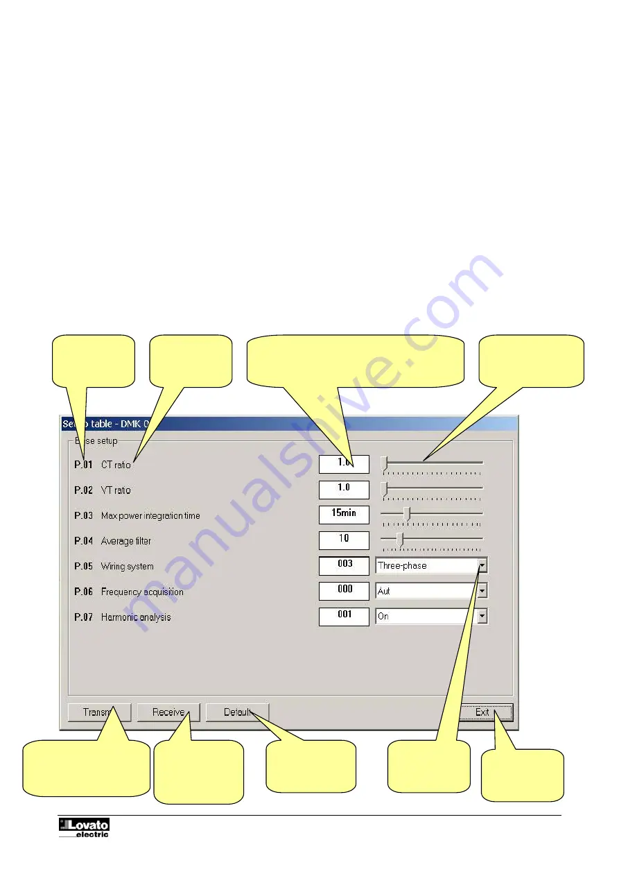
You can view and modify the setup parameters of the multimeters from the specific 

Parameters

 menu. This 

method of accessing DMK settings is handier and more immediate compared with direct access from the 
front keypad of the multimeters as, using the PC; the following are displayed: 
 

• 

Code of the parameter 

• 

Description in the language set 

• 

Value set 

• 

Graphic bar or drop-down box with possible options 

 
The parameters have been grouped in four menus that reflect the organization described in the operations 
manual and in the Addendum of the DMK. The following four menus are available: 
 

• 

Basic setup (basic settings such as CT, VT ratio, etc.) 

• 

Advanced setup (settings of the digital outputs) 

• 

Capacitor overload setup (parameters relating to the capacitor protection function). 


Basic setup  


Fig. 9.1 – Parameters-Basic setup  


Drop-down box 
with possible 
options 

Transmits the values 
displayed to the DMK and 
saves them. 
Enabled only with 
password

Receives the 
values from the 
DMK and displays 
them in the 
window  

Resets the factory 
default values 

Closes the 
setup window 

Code of the 
parameter  

Description  

Numeric value of the parameter. Highlighted in 
yellow if different from the factory-set default 
value. Double clicking on this box, you can set the 
parameter with the numeric keypad 

Graphic bar. 
Drag  this with the 
mouse to modify the 
setting  

Summary of Contents for DMK40

Page 1: ...n diagram direct 3 Basic principles 5 Main window 5 System configuration 6 Important note 9 Display menu 10 Data collection 10 Graphs 11 Front panel 14 Password 14 Communication menu 15 Online 15 Offl...

Page 2: ...and be familiar with Windows operating system commands The software is delivered on a CD with two different installation procedures The standard installation procedure used with the first releases of...

Page 3: ...onverter as indicated in the Connection diagrams paragraph below Comply scrupulously with the polarity of the Rs485 cables 4 We recommend use of a Rs232 Rs485 converter furnished by Lovato If you inte...

Page 4: ...Serial port settings window while for the DMK it is selected with parameter P 42 see Addendum The connection polarity of the DMKs and of the converter to the RS 485 bus must be correct all the A term...

Page 5: ...vidual measurement can be displayed and printed Main window The main window of the program contains all the menus and the toolbars for access to the various functions As they may modify the configurat...

Page 6: ...ystem configuration is a very important phase as regards definition of software functioning In particular if several multimeters are connected attention must be paid to programming the parameters of e...

Page 7: ...op If the selected measure indicates all three phases it is sufficient the measure value of one of the three phases is greater than threshold 1 to trigger the datalogger The same procedure is done to...

Page 8: ...ntly saved record is lost Transmits the settings made Note on transmitting the settings all the data saved in the DMK40 will be lost Receives the settings saved in the DMK40 View the DMK real time clo...

Page 9: ...figure 2 2 When using modem connection all this setting can be used only if the remote connection is done always to the same DMK network that is if there is only one record in the Modem index because...

Page 10: ...th the Display Data collection menu or clicking on the matching icon on the toolbar Fig 3 1 Display Data collection Sampling date and time Number of records selected Values of the variables sampled Di...

Page 11: ...aph menu or click on the matching icon of the toolbar This type of graph is very similar to t hat of an oscilloscope The time is indicated on the X horizontal axis The horizontal time scale is common...

Page 12: ...Code MSGB202 0500 doc 18 06 2004 P 12 20...

Page 13: ...Code MSGB202 0500 doc 18 06 2004 P 13 20...

Page 14: ...d or holding down of the keys Note The quality of the graphic representation of the front panel may vary according to the graphic resolution of your PC and or the monitor settings used Fig 7 1 Display...

Page 15: ...dow The system passes automatically in Offline mode when the user opens the Configuration window Modem Call To connect to one or several DMK via a couple of modems it is necessary to select the Modem...

Page 16: ...shaking messages with the answering modem At the end of this procedure if everything has been carried out correctly the PC status bar will show a message informing the user that connection has taken p...

Page 17: ...the DMK The following four menus are available Basic setup basic settings such as CT VT ratio etc Advanced setup settings of the digital outputs Capacitor overload setup parameters relating to the ca...

Page 18: ...eful when programming a set of multimeters with the same settings or when you want to file the original settings of a system To save the parameters on disk select the Parameters Save to file menu and...

Page 19: ...r the confirmation message and then disconnect the modem from the PC and connect it to the DMK The PM EXE program transmits the following configuration string to the modem AT E0 N6 U6 W0 CR commands v...

Page 20: ...below Click on Dial At this point the modem at the PC end calls the DMK modem After a few rings the DMK modem and the program switch automatically to the online mode To end the connection choose Modem...

Reviews: