Lorex Vantage LZC7091 Instruction Manual Download Page 23

13

Installation

English

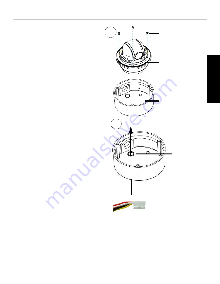
3. Remove the base attachment 

screws (3x) and remove the 
camera from the camera base.

Base 
attachment 
screws

Camera

Camera base

3

4.

Cable hole

4

6-Pin Connector

Remove the rubber plug on 
the bottom of the camera base 
and run the 6-pin connector 
through the cable hole. 

5. Drill holes for the mounting 

screws (x4) and the cable and 
run the cable through the hole. 

Summary of Contents for Vantage LZC7091

Page 1: ...www lorextechnology com 10X PAN TILT ZOOM CAMERA LZC7091 Copyright 2013 Lorex Technology Inc Instruction Manual English Version 4 0 RETAIL INDUSTRY BUSINESS BUSINESS HOME OUTDOOR...

Page 2: ...QUALIFIED SERVICE PERSONNEL The lightning flash with arrowhead symbol within an equilateral triangle is intended to alert the user to the presence of uninsulated dangerous voltage within the products...

Page 3: ...vice for warranty matters 1 888 425 6739 1 888 42 LOREX Tech Support for technical installation issues 1 877 755 6739 1 877 75 LOREX Mexico 001 800 681 9263 001 800 514 6739 International 800 425 6739...

Page 4: ...les produits guides d utilisation guides de d part rapide et FAQ www lorextechnology com support En ligne Hay 2 maneras f ciles de comunicarse con nosotros Norte Am rica Atenci n al cliente para asun...

Page 5: ...ology com support If you require further installation assistance please visit www lorextechnology com installation or contact a professional installer Please note that once the components of this prod...

Page 6: ...de ce produit vous ne pouvez pas retourner celui ci directement au magasin sans son emballage original Favor de leer la gu a de instalaci n r pida y la gu a del usuario antes de instalar este producto...

Page 7: ...or remote operation Removable camera base for easier and safer installation 100ft all in one extension cable included for installation location flexibility 1 This camera features an ultra low light se...

Page 8: ...allation under a sheltered environment is recommended Do not disassemble the camera Do not point the camera directly towards the sun or a source of intense light Use only the supplied regulated power...

Page 9: ...ith your DVR 16 4 1 Initial Setup 16 4 2 Controlling the Camera 17 4 3 PTZ Presets and PTZ Cruise 19 4 4 Setting PTZ Presets on the ECO2 DVR 19 4 5 Selecting PTZ Presets on the ECO2 DVR 20 4 6 Deletin...

Page 10: ...iv...

Page 11: ...NG STARTED 100ft BNC Power RS485 Extension Cable Mounting Screw Kit 13V DC Power Adapter Instruction Manual Camera Wall Mount Kit Foam Pad 3ft BNC Power RS485 Cable Before you start ensure you have re...

Page 12: ...era to your DVR and test the PTZ controls before permanent installation 6 Pin Connector Male BNC DVR Video Input RS485 Red Black Female DC Power Power adapter 1 2 3 4 DVR RS485 Ports 3ft BNC Power RS4...

Page 13: ...n below Dome cover Base attachment screws Camera Camera base Removing the camera from the case NOTE Do not use force when pulling out the 6 pin connector The 6 pin connector has a release latch under...

Page 14: ...the RS485 connectors to the RS485 ports on the alarm block on your DVR The layout of the alarm block may differ depending on your DVR model common terms include RS485 RS422 or PTZ The RS485 connectors...

Page 15: ...easily removed they may become disconnected and affect control of the camera Use wire strippers not included to expose more of the wires if needed 7 Connect the male BNC connector on the 100ft extens...

Page 16: ...ault ID 1 Default Baud Rate 2400 Default Protocol Pelco D For details on setting up your DVR with the PTZ camera see Controlling the PTZ Camera with your DVR on page 16 You will not need to change the...

Page 17: ...once installed It is very difficult to change the protocol information once the camera is installed Camera is capable of seeing in extremely low light conditions 0 02 Lux but it cannot see in total da...

Page 18: ...VR or use the guidelines below to extend the RS485 signal BNC video and PTZ control RS485 wires can be extended an additional 250ft 76m up to a maximum length of 350ft 106m Video quality may decrease...

Page 19: ...ed to the top of the pendant cap spares are included Firmly insert the pendant cap on to the wall mount bracket and twist to tighten all the way Insert the bracket screws 3x to secure pendant cap to w...

Page 20: ...nt screws 3x and remove the camera from the camera base Base attachment screws Camera Camera base 4 5 Remove the rubber plug on the bottom of the camera base and run the single end of the cable throug...

Page 21: ...crews 3x then reattach the dome cover by rotating it clockwise 6 NOTE Make sure power adapter is disconnected before connecting the 6 pin connector Camera will begin moving immediately when power adap...

Page 22: ...ng this method Use the included wall mount for outdoor installations Camera can be installed directly to a ceiling To install the camera 1 Foam Pad Cable and mounting screw cutouts 1 Remove the cutout...

Page 23: ...the camera base Base attachment screws Camera Camera base 3 4 Cable hole 4 6 Pin Connector Remove the rubber plug on the bottom of the camera base and run the 6 pin connector through the cable hole 5...

Page 24: ...ors if installing the camera in drywall 7 Connect the 6 pin connector to the camera 6 Pin Connector 7 NOTE Make sure power adapter is disconnected before connecting the 6 pin connector Camera will beg...

Page 25: ...the dome cover by rotating it clockwise Remove protective vinyl from dome cover 9 10 Connect the cables For details see Connecting the Camera on page 2 For details on DVR setup see Controlling the PT...

Page 26: ...s LH130 Series For other DVR models check your instruction manual for details 4 1 INITIAL SETUP In the initial setup process you will input the camera s protocol information into your DVR This enables...

Page 27: ...save your settings 4 2 CONTROLLING THE CAMERA TIP Turn off motion detection on your DVR for the channel with the PTZ camera connected Otherwise the DVR will detect the PTZ movement as motion See your...

Page 28: ...decrease the pan and tilt speed Camera Pre set controls see page 19 ATTENTION This PTZ camera is designed tilt up and down within a range of 155 Tilting less than 10 or greater than 165 away from the...

Page 29: ...NOTE These features may not be available on all DVR s Check your DVR instruction manual for details 4 4 SETTING PTZ PRESETS ON THE ECO2 DVR 1 Using the direction keys zoom focus and iris settings move...

Page 30: ...delete the preset and click Save to save your changes 4 7 STARTING STOPPING PTZ CRUISE ON THE ECO2 DVR When PTZ cruise is enabled the camera will cycle through saved presets You must set and save pre...

Page 31: ...r details PTZ protocol information on this camera is set using DIP switches on the bottom of the camera DIP switches represent binary values This means that they are either On 1 or Off 0 The DIP switc...

Page 32: ...ews 3x and remove the camera base See illustration below Dome cover Base attachment screws Camera Camera base Removing the camera from the case 5 2 SETTING THE CAMERA ID The camera ID is how the DVR i...

Page 33: ...FF OFF OFF OFF 8 OFF OFF OFF ON OFF OFF OFF OFF 9 ON OFF OFF ON OFF OFF OFF OFF 10 OFF ON OFF ON OFF OFF OFF OFF 11 ON ON OFF ON OFF OFF OFF OFF 12 OFF OFF ON ON OFF OFF OFF OFF 13 ON OFF ON ON OFF OF...

Page 34: ...nal sent to the camera The camera supports Pelco D and Pelco P protocols Protocol and baud rate are set using switches 1 2 on the smaller DIP switch panel See the table below Protocol and Baud Rate Sw...

Page 35: ...02 Lux in Black and White Lens Lens Type Auto Focus 3 8 38mm F 1 8 S N Ratio 50db AGC Off Iris Auto Iris Termination BNC Video RS485 DC Power Video Output Composite 1 0Vpp 75ohm Power Requirement 12V...

Page 36: ...26 Dimensions 7 DIMENSIONS Units mm Camera Camera and Wall Mount...

Page 37: ...re power adapter is the original one provided Do not use other power adapters with this product as this will void the warranty No image or camera image is unclear Dome cover is dirty Clean the dome co...

Page 38: ...ed properly Check your extension cable run PTZ protocol details are not configured in DVR See your DVR instruction manual for details Multiple PTZ cameras are using the same camera ID This will either...

Page 39: ......

Page 40: ...R16 EXPAND AND CUSTOMIZE YOUR SYSTEM WITH A FULL RANGE OF CAMERAS ACCESSORIES Accessories www lorextechnology com Specialty Cameras Wireless Cameras Dome Cameras Digital Video Recorders Simulated Came...

Reviews: