Water / Air Cooling Selection Button (14)
When using the integrated water cooling system with a water cooled torch, select the ‘water’ option
(16). This will activate the water cooler power (the water cooler must also be switched on the rear
panel) and the water cooling protection system. If using air cooled torch, select ‘Air’ option (15).
Note the welding machine comes standard with a water cooled torch system. Operating a water
cooled torch without water cooling will quickly cause serious damage to the torch. Damage to torch
or components due to lack of water is not covered under machine warranty.
MMA settings
Hot start (19)
Hot start provides extra power when the weld starts to counteract the high resistance of the electrode
and workpiece as the arc is started. setting range (0-10).
Arc force (21)
An MMA welding power source is designed to produce constant output current (CC).This means
with different types of electrode and arc length; the welding voltage varies to keep the current
constant. This can cause instability in some welding conditions as MMA welding electrodes will have
a minimum voltage they can operate with and still have a stable arc.
Arc Force control boosts the welding power if its senses the welding voltage is getting too low. The
higher the arc force adjustment, the higher the minimum voltage that the power source will allow.
This effect will also cause the welding current to increase. 0 is Arc Force off, 10 is maximum Arc Force.
This is practically useful for electrode types that have a higher operating voltage requirement or joint
types that require a short arc length such as out of position welds.
TIG settings
TIG 2T/4T Trigger Control
2T Mode (17)
The trigger is pulled and held on to activate the welding circuit, when the trigger is released, the
welding circuit stops.
4T Mode (18)
This is known as ’latching’ mode. The trigger is pulled once and released to activate the welding
circuit, pulled and released again to stops the welding circuit. This function is useful to longer welds as
the trigger is not required to be held on continuously. TIG series of welding machines also has more
current control options that can be used in 4T mode.
TIG Parameter Setting (23)
Pre gas flow setting indicator (1)
Pre-flow controls the period shielding gas will flow for when the torch is triggered before the arc starts.
This purges the work area of atmospheric gas which could contaminate the weld before the weld
starts. Unit(S) and setting range (0.1-2S).
Start current setting indicator (2)
Available in 4T trigger mode, sets a welding current 10-100% of the main welding current activated
when the trigger is held on to ‘latch’ the trigger before the main weld current is started. Once the
trigger is released, the current will go through the upslope (3) period if it is set, to the main welding
current (4).
Up slope setting indicator (3)
When the trigger is activated, the welding current will increase gradually over the time selected
up to the set main welding current (4). Unit(S) and setting range (0-10.0S).
3.2
Power
supply input
Connection
The TIG welding machine is designed to operate on a 3phase 380-400-440V AC power supply.
When the power supply voltage is over the safe work voltage, there are over voltage and under
voltage protection inside the welder, the alarm light will on, at the same time, the current output will
be cut off.
If the power supply voltage continually goes beyond the safe work voltage range, it will shorten the
welder life-span. The below measures can be used:
-
Change the power supply input net. Such as, connect the welder with the stable power supply
voltage of distributor;
-
Induce the machines using power supply in the same time;
- Set the voltage stabilization device in the front of power cable input.
3.3
Installation
& Operation
for MMA
Welding
3.3.1
Set up
installation
for MMA
Welding
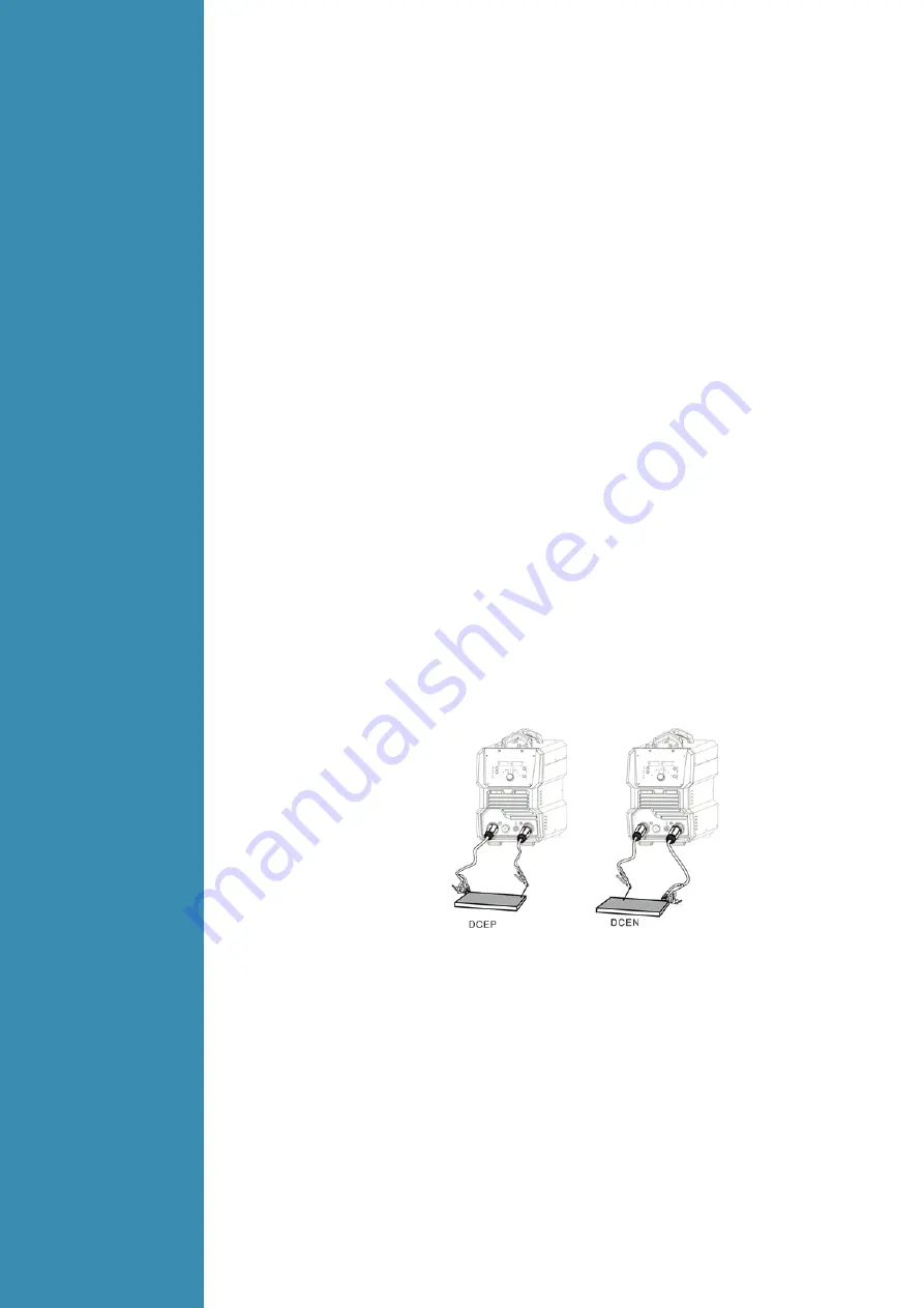
Connection of Output Cables Two sockets are available on this welding machine. For MMA welding
the electrode holder is shown be connected to the positive socket, while the earth lead (work piece) is
connected to the negative socket, this is known as DCEP. However various electrodes require a
different polarity for optimum results and careful attention should be paid to the polarity, refer to the
electrode manufacturers information for the correct polarity.
DCEP: Electrode connected to “+”output socket.
DCEN: Electrode connected to“-” output socket.
MMA (DC): Choosing the connection of DCEN or DCEP according to the different electrodes. Please
refer to the electrode manual.
MMA (AC): No requirements for polarity connection.
(1) Connect the earth lead to “-”, tighten clockwise;
(2) Connect the earth clamp to the work piece. Contact with the work piece must be firm contact
with clean, bare metal, with no corrosion, paint or scale at the contact point.
(3) Connect the electrode lead to “+”, tighten clockwise;
(4) Each machine is equipped with a power cable should be based on the input voltage welding
power cable connected to the appropriate position, not to pick the wrong voltage;
(5) With the corresponding input power supply terminal or socket good contact and prevent
oxidation;
(6) With a multi meter measure the input voltage is within the fluctuation range;
(7) The power ground is well grounded.


