42
4
2
1
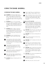
WIRING DIAGRAM
60-SH-6-FAS-2
Elesa CFSQ,
Interlock safety switch
Black
Black
Ignition off
Igntion off
Grey
Blue
WIRING DIAGRAM, EMERGENCY STOP /
SAFETY SWITCH
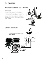
WATER COOLING
The water cooling of the blade is controlled by a lever
located on the side plate at the operator side. In its start-
ing position, the lever points at a right angle from the side
plate. To release the water flow, the lever is pulled back. The
flow of the water cooling is controlled by moving the cool-
ing tube in the narrowing slot in the motor bracket. Move
the tube inwards or outwards in the slot until you reach the
desired cooling level.
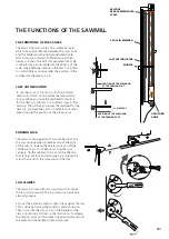
THE FUNCTIONS OF THE SAWMILL

