background image

16 //ADJUSTABLE BED FRAME - OWNER’S MANUAL

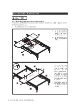
1. Turn over the Base Plat-

form 

(H)

  DQG OD\ LW ÀDW

across the center of the

Bed Frame. The Net

should face downwards.

2. Ensure that the Platform

is correctly positioned.

There should be 2 Mount-

ing Holes on each Side

Rail

 (A, B) 

either side of

the Platform.

3. Use 4 Platform Screws 

(N)

WR¿[WKH3ODWIRUPE\KDQG

Turn each screw until it is

hand-tight.

H

A

B

N

STEP 5: MOUNTING THE BASE PLATFORM

1. Lay the Base Platform

(H)

upside down across

the Bed Frame. The Net

should face upwards.

2. Lay the Control Box 

(I) 

in-

side the Net on the Base

Platform.

H

I

BASE

4x

CAUTION

Risk of minor or moderate injury through tripping 

While mounting the Platforms, you may have to step over the Power Cable. Tripping over the 
Cable may lead to injury. 
• Be careful not to trip over the Cable

17

ADJUSTABLE BED FRAME -  OWNER’S MANUAL //

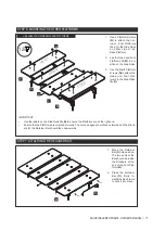
STEP 7: ATTACHING THE RETAINER BAR

1. Move the Retainer

Bar 

(O) 

into position.

The two ends of the

Bar should be inside

the Brackets at the

end of the Foot Plat-

form

 (M).

2. Press the Retainer

Bar 

(O) 

¿UPO\ WR-

wards the Bed Frame

to click it into place.

1. Use 4 Platform Screws

(N)

to attach the nar-

rower, Inner Platforms

(G, L)

 to the Side Rails

on either side of the

Base Platform.

2. Lay the Head and Foot

Platforms 

(F, M) 

in po-

sition on the Side Rails. 

3. 8VHWKH¿QDO3ODWIRUP

screws

 (N) 

to attach the 

Head and Foot Plat-

forms to the Side Rails.

(A, B).

STEP 6: MOUNTING THE OTHER PLATFORMS

M

O

IMPORTANT:

Use the labels on the Side Rails 

(A, B)

 to ensure the Platforms are at the right end.

Ensure the the Platforms are oriented correctly. The curved edges should face outwards and the Brack-

ets for the Retainer Bar should face downwards.

INNER

FOOT

HEAD

G

L

N

M

F

H

12x

USE LABELS ON SIDE RAILS AND PLATFORMS

18 //ADJUSTABLE BED FRAME - OWNER’S MANUAL

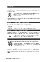
NOTICE

If the Bed Frame is too close to the wall (or touching it), it may collide during movement. To avoid 
damage to the Bed Frame and the wall, ensure a small distance is kept.

STEP 8: CONNECTING THE POWER CABLE

NOTICE

Stretching the Power Cable may damage it. This may lead to malfunctions with the Bed Frame. 

1. Connect the Power Cable

  from 

the Control Box

 to the cable

of the Power Converter

 (J).

2. Connect the second Power Ca-

ble to the Power Converter, then 

to the mains.

3. Lay the Power Cable along the

wall behind the Bed Frame to

minimize the risk of tripping.

NOTICE

Ensure the Cable is plugged into the mains properly. Bad connections can damage the system.

1

2

Summary of Contents for COSMO Austin

Page 1: ...Document Version 6 July 2021 OWNER S MANUAL ADJUSTABLE BED FRAME...

Page 2: ...or reproduce the document are reserved No part of this manual may be reproduced mechanically electronically or by other means in any form without prior written permission of LOGICDATA Electronic Softw...

Page 3: ...imals are in the proximity of the Bed Frame when operating it Ensure nothing obstructs the Bed Frame s range of motion e g night stands or open windows Do not sit directly on any Platform when operati...

Page 4: ...r Platforms at any time Exceeding the recommended maximum load could damage the product and void the warranty Usage outside of the intended use described in this Owner s Manual is only allowed with wr...

Page 5: ...WARNING The signal word WARNING indicates a hazardous situation which if not avoided could result in death or serious injury NOTICE The signal word NOTICE indicates a situation that will not lead to...

Page 6: ...ommended by the manufacturer Never operate the Bed Frame if it or any parts have a damaged Cable or Plug are not work ing properly have been dropped or damaged or dropped into water Return the bed for...

Page 7: ...ospheres Operating the Adjustable Bed Frame in potentially explosive atmospheres may lead to death or serious injury through explosions Read the relevant directives to determine whether an atmosphere...

Page 8: ...at all times Product documentation consists of this Owner s Manual and any other relevant documents supplied by the manufacturer Documenta tion must always be kept complete and legible 2 INTRODUCTION...

Page 9: ...ld result in the prod uct exceeding the RF exposure requirements This may void your authority to use the product SERVICING OF DOUBLE INSULATED PRODUCTS In a double insulated product two systems of ins...

Page 10: ...e all the parts are present and in perfect condition If any part is damaged or missing FRQWDFW 2 7 RX FDQ QG WKH UHOHYDQW FRQWDFW GHWDLOV DW WKH EHJLQQLQJ RI WKH 2ZQHU V 0DQXDO QVXUH WKDW WKH ER HV DU...

Page 11: ...OWNER S MANUAL QUICK START GUIDE OWNER S MANUAL REMOTE CONTROL 2x AAA BATTERIES HEAD PLATFORM BASE PLATFORM F H 16X PLATFORM SCREW O N RETAINER BAR L INNER PLATFORM M FOOT PLATFORM HEAD BASE INNER FOO...

Page 12: ...e product NOTICE QVXUH DOO SDUWV DUH DW URRP WHPSHUDWXUH 3DUWV WKDW DUH WRR FROG RU KRW PD D HFW DVVHPEO CAUTION Risk of minor or moderate injury through cutting Contact with sharp edges may lead to m...

Page 13: ...DO NOT REMOVE STRAPPING TAPE USE LABELS ON SIDE RAILS DO NOT REMOVE PROTECTIVE MATERIAL STEP 1 PREPARING THE OUTER FRAME WALL Lay the Crossbars D and Side Rails A B on the ground as shown in the pictu...

Page 14: ...e Knob counter clockwise until it is hand tight D E REMOVE STRAPPING TAPE REMOVE PROTECTIVE MATERIAL CAUTION Risk of minor or moderate injury through crushing The Side Rails are not secured while they...

Page 15: ...e injury through crushing While screwing in the Crossbar Knobs you will need to lift the moving parts of the Side Rails Allowing these parts to fall may lead to minor or moderate injury through crushi...

Page 16: ...Platform Screws N WR WKH 3ODWIRUP E KDQG Turn each screw until it is hand tight H A B N STEP 5 MOUNTING THE BASE PLATFORM 1 Lay the Base Platform H upside down across the Bed Frame The Net should fac...

Page 17: ...ide Rails on either side of the Base Platform 2 Lay the Head and Foot Platforms F M in po sition on the Side Rails 3 8VH WKH QDO 3ODWIRUP screws N to attach the Head and Foot Plat forms to the Side Ra...

Page 18: ...OTICE Stretching the Power Cable may damage it This may lead to malfunctions with the Bed Frame 1 Connect the Power Cable from the Control Box to the cable of the Power Converter J 2 Connect the secon...

Page 19: ...INSERTING THE BATTERIES NOTICE Replace the batteries in the Remote Control once a year Do not use rechargeable batteries Insert two 1 5V AAA batteries into the Re mote Control and slide the cover into...

Page 20: ...with your product may vary NOTICE Pressing too many Buttons in a short space of time can cause damage to the system DLW RQH VHFRQG EHWZHHQ SUHVVLQJ GL HUHQW XWWRQV CAUTION Risk of minor or moderate i...

Page 21: ...fore operation Ensure the Bed Frame has been unplugged for at least 10 seconds then proceed as follows 1 Plug the Bed Frame into the mains This will automatically switch it to Pairing Mode for 30 minu...

Page 22: ...o move to then release 2 Wait for the Bed Frame to move to the saved Memory Position MOVING THE BED FRAME TO THE SLEEPING POSITION 3 The Sleeping Position is the Bed Frame s lowest position While in t...

Page 23: ...ed CAS on each Control Box 3 Ensure the Cable is Routed so that it does not interfere with the movement of the Bed Frames 4 Reconnect the Bed Frames to the Power Outlet If the Bed Frames do not move t...

Page 24: ...le To lift the Bed Frame 1 QVXUH WKDW WKH HG UDPH KDV UVW EHHQ PRYHG WR WKH 6OHHSLQJ 3RVLWLRQ 2 Stand at opposite sides of the Bed Frame long sides and grip the Base Platform NOTICE Moving the Bed Fra...

Page 25: ...LQJ WHFKQLFDO GL FXOWLHV FRQWDFW 2 7 XVLQJ WKH GHWDLOV RQ SDJH 7 CLEANING AND MAINTENANCE WARNING Moderate risk of death or serious injury through electric shocks Leaving the Bed Frame plugged in whil...

Page 26: ...oes out then plug it back in 4 Replace the batteries in the Remote Control If power cannot be restored an Emergency Lowering is required Proceed as follows 1 Unplug the Power Converter from the power...

Page 27: ...You will need to perform separate Emergency Lowerings for Bed Frames con nected by the Sync Cable CODE 2 X Click 1 X Click 4 6 X Click DEFINITION Normal operation Continue to operate the Bed Frame The...

Page 28: ...product should not be disposed of with regular household waste Adhere to the disposal procedures for the raw materials and components used Recycle as many parts as possible Careless or incorrect dispo...

Reviews: