background image

17

12

TIME SERVER CONNECTION STATUS

After the console has connected to the internet, it will 

attempt to connect to the internet time server to obtain 

the UTC time. Once the connection succeeds and the 

console's time has been updated, the “   ” icon will 

appear on the LCD.
The time will automatically synchronize Internet time server at 12:00AM and 12:00PM per day. 

Also you can press the 

[REFRESH ]

 key to get the internet time manually within 1 minute. 

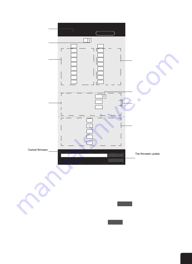
ADVANCE SETTING IN WEB INTERFACE

Press 

"ADVANCED"

 key at the top of web interface to enter the advance setting page, this 

page allow you to set and view the calibration data of the console, as well as update the 

firmware version on PC web browser.

Upload

Browse

Firmware version: 1.00  

-560~ 560hpa / -16.54 ~ 16.54inHg / -420 ~ 420mmHg

Setting Range: 

Temperature

o

C

Outdoor

Indoor

CH 1

CH 2

CH 3

CH 4

CH 5

CH 6

CH 7

Humidity %

Relative Pressure Offset:

Absolute Pressure Offset:

hpa

Range: -20 ~ 20

(Default: 0.0)

Current offset: 10

Current offset: -9

Current offset: -5

Current offset: 2

Current offset: -2

Current offset: 3

Current offset: -2

Current offset: 1.2

Current offset: -5

Current offset: -0.2

Current offset: -3

Current offset: -20.1

Current offset: -10

Current offset: 11.5

Current offset: -3

Current offset: -3

(Default: 0)
Current offset: 10

(Default: 0)

Current offset: 0.2

Current offset: -5

Current offset: 1

Pressure

Range: -20.0 ~ 20.0

o

C

-36.0 ~ 36.0

o

F (Default: 0.0) 

*UV gain:

Range: 0.01 ~ 10(Default: 1.00)

Current gain: 1.1

*Light gain:

Range: 0.01 ~ 10(Default: 1.00)

Current gain: 1.1

* Depends on the model

*Wind speed gain:

*Wind direction:

*Rain gain:

Range: 0.5 ~ 1.5(Default: 1.00)

Range: -10 ~ 10(Default: 0

o

)

Range: 0.5 ~ 1.5(Default: 1.00)

Current gain: 0.85

Current offset: 2

o

Current gain: 0.75

SETUP

ADVANCED

Select setting unit

Press "SETUP" icon to 

Setup page

Outdoor and Ch 1~7 

temperature calibration 

section

Pressure calibration 

section

version

function only available 

in PC web browser

ADVANCED page

Select setting unit

The rain, wind speed, UV and Light 

calibration use gain method. The 

wind direction is +/- 10 offset.

Outdoor and Ch 1~7 humidity 

calibration section

Current offset value is the value

that you set before to offset the 

pressure reading.

SETTINGS

CALIBRATION

1. User can input the offset and/or gain values for different parameters while current offset and 

gain values are shown next to their corresponding blank.

2. Once completed, press 

Apply

 at the bottom of the SETUP page

The current offset value will show the previous value that you entered, please input the new 

value in the blank if any changes needed, the new value will effective once you press 

Apply


icon in SETUP page.

CALIBRATION

1.  You may enter or change the offset and gain values for different measurement parameters, 

while viewing the current offset and gain values next to the corresponding boxes.

2.  Once you have completed your calibrations, press the                    button on the SETUP tab.
3.  The current offset value will update to show the value that you entered (instead of the default 

value). If you want to change the value, you can enter a new value in the box beside the number 

(as in step 1). To update the value, again, press                    in the SETUP tab.

NOTE: We do not recommend calibration of most values with the exception of Relative 

Pressure, which must be correctly calibrated to reflect your distance above sea level to 

account for altitude effects.

6

1.  Remove the battery door of the console.

2.  Insert 3 new AAA batteries as per the polarity indicated,

3.  Replace the battery door.

BUILT-IN MEMORY

The console has built-in FLASH memory that holds the vital settings. These include:


-

Time Zone, DST status, Time SYNC status, WI-FI and Weather server setting, Latitude / 

Longitude, Hemisphere setting, Calibration values, and Sensor ID of paired sensor(s)

RESET AND FACTORY HARD RESET

 To reset the console and start again, press the 

[ RESET ]

 key once. To hard reset the 

console and resume factory settings, press and hold the 

[ RESET ]

 key for 6 seconds

RESYNCHRONIZE SENSORS

Press the 

[ SENSOR / WI-FI ]

 key once for the console to enter sensor Synchronization mode, 

and the console will re-register all the sensors that have already been registered to it before. 

i.e. the console will not lose the connection of the sensors that you’d paired up before.

CHANGING BATTERIES AND MANUAL PAIRING OF SENSOR

Whenever you changed the batteries of the wireless indoor or 7-in-1 weather sensor, re-

synchronization must be done manually.

1.  Change all the batteries to new ones in the sensor.

2.  Press 

[ SENSOR / WI-FI ]

 key on the console to enter sensor synchronization mode.

3.  Press 

[ RESET ]

 key on the wireless indoor or 7-in-1 weather sensor.

SYNCHRONIZING ADDITIONAL WIRELESS SENSOR(S) (OPTIONAL)

The console can support up to 7 additional wireless sensors.

1.  Press the 

[ SENSOR / WI-FI ]

 key once on the console to enter synchronization mode.

2.  Press the 

[ RESET ]

 key on the new sensor, and wait for a few minutes for the new sensor 

to paired to the console.

NOTE:

 -Channel number of the indoor sensor must not be duplicated among the sensors. Please refer 

to “

INSTALL WIRELESS INDOOR SENSOR

” for details

 -This console can support different type of additional wireless sensor, e.g. soil moisture and 

pool sensor. If you would like to pair up additional sensors, please check with your retailer for 

more detail.

POINTING THE WIRELESS 7-IN-1 SENSOR TO SOUTH 

The outdoor 7-IN-1 sensor is calibrated to point to North for the maximum accuracy. However, 

for the user's convenience (e.g. users in the Southern hemisphere), it is possible to use the 

sensor with the wind vane pointing to South.

1.  Install the 7-IN-1 wireless sensor with its wind meter end pointing to South. (Please refer to 

INSTALLATION OF THE WIRELESS SENSOR

 section for mounting details)

2.  Select "S' in hemisphere section of the setup UI setup page. (Please refer to 

SETUP THE 

WEATHER SERVER CONNECTION

 section for setup details)

3.  Press 

Apply

 icon to confirm and exit.

NOTE: 

Changing the hemisphere setting will automatically switch the direction of the moon phase on 

the display.

Summary of Contents for LOWSC710SWB

Page 1: ...7 IN 1 WIRELESS WEATHER STATION WITH WI FI AND SOLAR PANEL USER GUIDE LOWSC710SWB ...

Page 2: ...arranty Coverage is subject to limits and exclusions See warranty for details SAFETY PRECAUTIONS PRODUCT FEATURES PACKAGE CONTENTS WEATHER CONSOLE OVERVIEW CONSOLE LCD DISPLAY OVERVIEW WIRELESS INDOOR HYGRO THERMO SENSOR OVERVIEW WIRELESS 7 IN 1 OUTDOOR SENSOR OVERVIEW INSTALLATION INSTRUCTIONS SETTING UP THE WIRELESS 7 IN 1 OUTDOOR SENSOR SETTING UP THE WIRELESS INDOOR HYGRO THERMO SENSOR SETTING...

Page 3: ... new and old batteries together Do not disassemble alter or modify the product Only use attachments or accessories with this product specified by the manufacturer Do not submerge the unit in water Dry the product with a soft cloth if liquid spills on it Do not subject the unit to excessive force shock duct extreme temperature or humidity Do not cover or block the ventilation holes with any objects...

Page 4: ... information directly from your own backyard instead of relying on a national weather station 4 Color LCD display with dimmable backlight 5 Can alert you to excessively high low indoor or outdoor temperatures or humidity high wind speeds extreme drops in barometric pressure high heat indexes low wind chills and high low dew points 6 Syncs with installed Wi Fi and online weather servers Weather Und...

Page 5: ... s LOGIA is a tradem Android and Goog Apple IOS and Ap Microsoft Window Microsoft Corpora Wi Fi WPA and W All other products owners used mer sponsorship endo Distributed by C 2020 C A IP SKU L 8 4381 Precise weather environmental information 12 24 hour weather forecasting Color LCD display screen with dimmable backlight Alerts for High low temperature indoor outdoor High low humidity indoor outdoo...

Page 6: ...ins useful information on the proper use and care of this product Please read this manual through to fully understand and enjoy its features and keep it handy for future use OVERVIEW CONSOLE XXXXXXXXXXXX XXXXXXXX Model No XXXXX 1 2 3 4 5 6 7 8 9 11 10 12 13 14 15 16 17 18 19 20 21 22 23 1 weather readings with advanced features such as high low alert alarm different weather index and MAX MIN recor...

Page 7: ... Wall mounting holder 13 CLOCK SET key 14 V INDEX key 15 Ʌ key 16 OFF LO HI key 17 Table stand 18 ALARMT key 19 ALERT key 20 Power jack 21 Battery compartment 22 C F key 23 RESET slide switch LCD DISPLAY 1 2 3 4 6 5 7 8 9 Display section 1 Outdoor temperature humidity 2 Wind direction speed 3 Indoor Ch temperature humidity 4 Weather index 5 UV index light intensity SUN 6 Weather forecast 7 Baromet...

Page 8: ... 2 3 9 4 RESET button 5 Battery Compartment 2 2 Wind direction speed 3 Indoor Ch temperature humidity 4 Weather index 5 UV index light intensity SUN 7 Barometer 8 Rain 9 Time Data moon phase Sunrise Sunset time WIRELESS INDOOR HYGRO THERMO SENSOR 1 2 3 4 5 1 Transmission status LED 2 Wall mounting holder 3 Channel slide switch 4 RESET key 5 Battery compartment 1 1 3 4 2 5 6 2 3 4 5 ...

Page 9: ...1 indoor sensor SETTING UP THE WIRELESS 7 IN 1 OUTDOOR SENSOR The wireless 7 in 1 outdoor sensor measures wind speed wind direction rainfall UV light intensity temperature and humidity 9 Wind direction vane 10 UV light sensor 11 Solar panel 12 Wind speed cups 3 7 8 10 11 9 12 1 Antenna 2 Radiation shield Thermo hygro sensor 3 Mounting parts fit for 35 40mm diameter pole 4 Battery door 5 RESET key ...

Page 10: ...ection rainfall UV light intensity temperature and humidity for you It s assembled and calibrated for your easy installation INSTALL RAIN COLLECTOR Rain Collector Installation 1 Align Lock grooves 2 Lock INSTALL BATTERIES Unscrew the battery door at bottom of unit and insert the batteries according to the polarity indicated Screw the battery door compartment on tightly NOTE The red LED will begin ...

Page 11: ...cally switch the direction of the moon phases on the display Pointing the wireless weather sensor toward the south will allow maximum sunlight on the solar panel especially during the winter season in the Southern Hemisphere POINTING THE WIRELESS 7 IN 1 OUTDOOR SENSOR TO SOUTH OPTIONAL 4 NOTE MOUNTING POLE AND DIRECTION ALIGNMENT Install the wireless 7 IN 1 sensor in an open location with no obstr...

Page 12: ...e effective press RESET key on the sensor sunlight rain or snow pairing failure during new console setup please power up RESET key on the main unit no need on sensors R SENSOR ou wish to hang the sensor on he wall mounting holder You by itself power jack at the back of the console the segments of the LCD will be shown momentarily ers sensor synchronization mode and AP mode refer to LESS INDOOR SEN...

Page 13: ... minutes for the new sensor to pair to the console NOTE Channel number of an indoor sensor must not be the same as another indoor sensor Please refer to Setting Up the Wireless Indoor Hygro thermo Sensor section for details POWERING UP THE CONSOLE 1 Remove the battery door of the console 2 Insert 3 new AAA batteries as per the polarity indicated 3 Replace the battery door BUILT IN MEMORY The conso...

Page 14: ...p Station key Router Add Router Search Security type Router Password WAP2 ROUTER_A Apply Language English Weathercloud Station ID Station key Mac address 00 0E C6 00 07 10 Press to search router Select the Wi fi router SSID you will connect to Manually enter the SSID if not on the list Select router s security type usually WAP2 Check to confirm upload to Weather Underground Enter new Station ID and ...

Page 15: ...n key that assigned by weathercloud Enter new Station ID and Station key that assigned by the corresponding weather server Manually enter the SSID if not on list Select time server Select time zone of your location Select the direction e g EU countries Longitude is East and US is West Select the sensor located hemisphere e g US and EU countries are also N Australia is S Reserved for validated weat...

Page 16: ...any nist time gov Server URL Time server setup 0 00 Time Zone CTION STATUS onnected to the internet it will e internet time server to obtain connection succeeds and the n updated the icon will lly synchronize Internet time server at 12 00AM and 12 00PM per day REFRESH key to get the internet time manually within 1 minute WEB INTERFACE y at the top of web interface to enter the advance setting page...

Page 17: ... the console will re register all the sensors that have alr i e the console will not lose the connection of the sensors t CHANGING BATTERIES AND MANUAL PAIRING OF SENS Whenever you changed the batteries of the wireless indoor synchronization must be done manually 1 Change all the batteries to new ones in the sensor 2 Press SENSOR WI FI key on the console to enter s 3 Press RESET key on the wireles...

Page 18: ...Station ID and Station Key Password for reference and to complete the setup process CREATE WEATHER SERVER ACCOUNT SETUP WI FI CONNECTION The console can upload weather data to WUnderground and or Weathercloud through WI FI router you can follow the step below to setup your device NOTE The Weather Underground and Weathercloud website are subjected to change without notice CREATE WEATHER UNDERGROUND...

Page 19: ...Weather underground s privacy terms 4 click Next to create your station ID and key 2 2 3 4 1 5 Jot down Your Station ID and Station key for the further setup step CREATE WEATHERCLOUD ACCOUNT 1 In https weathercloud net enter your information in Join us today section then follow the instructions to create your account NOTE Use the valid email address to register your account 2 Sign in weathercloud ...

Page 20: ...nter all the information in Create new device page for the Model selection box select the W100 Series under CCL section for the Link type selection box select the Pro Weather Link Once you have completed click Create 8 CREATE WEATHERCLOUD ACCOUNT 1 In https weathercloud net enter your information in Join us today section then follow the instructions to create your account NOTE Use the valid email ...

Page 21: ...w the steps below to update your device s Function or Wi Fi System Firmware 1 Download the latest version of the firmware Function or Wi Fi and save it to your PC Remember where you saved the file 2 Press and hold the WI FI SENSOR button for six 6 seconds to put the display console into AP mode then connect the PC to the console refer to steps in Setting Up Wi Fi Connection on page 14 3 Click the ...

Page 22: ... between date and year display 4 Click the corresponding Upload button to transfer the updated file to the console 5 The file will install automatically once it is uploaded You can view update progress on the display console in the wind direction section the number displayed will correspond to the percentage completed so 50 50 and so on 6 The console will restart once the update completes NOTES Yo...

Page 23: ...ow Icon Rising Steady Falling Too cold Comfortable Too hot No signal Weak signal Good signal Setting the Alarm If you d like to use your display console as an alarm clock follow these instructions to set the alarm time 1 In normal operating mode press and hold the ALARM button for two 2 seconds until the alarm hour starts flashing This indicates that you have entered the alarm time setting mode 2 ...

Page 24: ...If the temperature outside rises above 176 F 80 C the LCD display will show the word HI in the temperature section If when the humidity level falls below 1 the LCD display will show the word LO in the humidity section If when the humidity level rises above 99 the LCD display will show the word HI in the humidity section TEMPERATURE Temperature Humidity Trends Northern Hemisphere Icons Southern Hem...

Page 25: ... air temperature and humidity levels to determine the approximate comfort level Northern Hemisphere Icons Southern Hemisphere Icons Moon Phase New Moon Waxing Crescent Moon First Quarter Moon Waxing Gibbous Moon Full Moon Waning Gibbous Moon Third Quarter Moon Waning Crescent Moon NOTE In alarm mode the icon will display on the LCD Temp Humidity Trend Arrow Icon Rising Steady Falling Too cold Comf...

Page 26: ...al time wind direction indicator Average gust wind speed TO SET THE WIND SPEED UNIT AND DIRECTION DISPLAY FORMAT 1 In normal mode press and hold WIND key for 2 seconds to enter into wind speed unit mode and the unit will flash Press or key to change the wind speed unit in this sequence m s km h knots mph 2 Press WIND key again to return to normal mode TO SELECT THE WIND DISPLAY MODE In normal mode...

Page 27: ...temporary signs and barricades blow over Severe widespread damage to vegetation and structures Debris and unsecured objects are hurled about 10 Trees are broken off or uprooted structural damage likely 11 Widespread vegetation and structural damage likely 12 Calm Light air Light breeze Gentle breeze Moderate breeze Fresh breeze Strong breeze High wind Gale Strong gale Storm Violent storm Hurricane...

Page 28: ... Some branches break off trees and some small trees blow over Construction temporary signs and barricades blow over Trees are broken off or uprooted structural damage likely Widespread vegetation and structural damage likely Severe widespread damage to vegetation and structures Debris and unsecured objects are hurled about 8 Gale 9 Strong gale 10 Storm 11 Violent storm 12 Hurricane force 62 74 km ...

Page 29: ...ress on foot is seriously impeded Some branches break off trees and some small trees blow over Construction temporary signs and barricades blow over Trees are broken off or uprooted structural damage likely Widespread vegetation and structural damage likely Severe widespread damage to vegetation and structures Debris and unsecured objects are hurled about Empty plastic bins tip over 8 Gale 9 Stron...

Page 30: ...ainfall record whenever you move and reinstall your wireless weather sensor to a different location LATIVE BAROMETRIC READING key to switch between ABSOLUTE RELATIVE barometric e rainfall and rain rate or 2 seconds to enter unit setting mode le the rainfall unit between mm and in and exit the setting SPLAY MODE ween the past hour midnight the current week f the current calendar month he last reset...

Page 31: ...ed by the outdoor sensor Corresponding exposure level and suggested protection indicator are also displayed Exposure level Suggest protection indicator SUNBURN TIME MODE To show the recommended sunburn time according to current UV level UV INDEX SUNBURN TIME TABLE Exposure level Low Moderate High Very high Extreme UV index 1 2 3 4 5 6 7 8 9 10 11 12 16 Sunburn time N A 45 minutes 30 minutes 15 min...

Page 32: ...g with the time and date when displaying the history data records HISTORY History Data for Past 24 Hours pressure MIN relative pressure MAX absolute pressure MIN absolute pressure MAX rain rate TO CLEAR THE MAX MIN RECORDS Press and hold MAX MIN key for 2 seconds to reset the current on display MAX or MIN records NOTE The LCD will also display the icon data records time date PAST 24 HOURS HISTORY ...

Page 33: ...ourly Rainfall 1mm 1000mm Rainfall 100mm 2 Under the current alert reading press and hold ALERT key for 2 seconds to enter alert setting and the alert reading will flash 3 Press Ʌ or V key to adjust the value or press and hold the key to change rapidly 4 Press ALERT key to confirm the value 5 Press ALARM key to toggle the regarding alert on off 6 Press ALERT key to step to next alert reading High ...

Page 34: ...is displayed in the outdoor temperature and humidity section or the corresponding CH section of the LCD console display this indicates that the batteries in your wireless weather sensor s are running low and should be replaced Make sure to replace all batteries at the same time CARE AND MAINTENANCE NANCE Y REPLACEMENT w battery indicator is displayed or CH section it indicates that the 7 IN 1 sens...

Page 35: ...version of any web browser that supports HTML 5 Supported sensors RF frequency RF transmission range 492 ft 150 m Time display HH MM SS General Specifications Wi Fi Communication Specifications Wireless Sensor Communication Specifications Barometer Display Function Specifications Time Function Specifications Hour format 12 hour or 24 hour Date display DD MM or MM DD Time synchronization method Synchron...

Page 36: ...In Out accuracy Resolution Display modes Current Memory modes Historical data of past 24 hours daily Max Min Alarm High Low Humidity Alert The following detail are listed as they are displayed or operate on the console Wind speed unit mph m s km h and knots Wind speed display range 0 112 mph 50 m s 180 km h 97 knots Resolution 0 1 mph 0 1 m s 0 1 km h 0 1 knots Speed accuracy 5 m s 0 5 m s 5 m s 6...

Page 37: ...lux 0 01 Kfc and 0 01 W m Memory modes Historical Data of past 24 hours Max Alarm Hi light intensity alert Display modes Current Memory modes Historical Data of past 24 hours Daily Max Min Alarm Feels like Hi Lo alert dew point Hi Lo alert heat index Hi alert wind chill Lo alert Wireless 7 in 1 Outdoor Sensor Specifications Dimensions W x H x D 12 7 x 11 7 x 8 5 322 x 296 x 217 mm Weight 1 5 lb 674...

Page 38: ...rdware defect arises and a valid claim is received within the Warranty Period the Company at its sole option and to the extent permitted by law will either 1 repair the Product defect at no charge using new or refurbished replacement parts 2 exchange the Product with a Product that is new or which has been manufactured from new or serviceable used parts and is at least functionally equivalent to t...

Page 39: ...NG TO THE CONTRARY AND TO THE MAXIMUM EXTENT PERMITTED BY APPLICABLE LAW THE COMPANY PROVIDES THE PRODUCT AS IS AND AS AVAILABLE FOR YOUR CONVENIENCE AND THE COMPANY AND ITS LICENSORS AND SUPPLIERS EXPRESSLY DISCLAIM ALL WARRANTIES AND CONDITIONS WHETHER EXPRESSED IMPLIED OR STATUTORY INCLUDING THE WARRANTIES OF MERCHANTABILITY FITNESS FOR A PARTICULAR PURPOSE TITLE QUIET ENJOYMENT ACCURACY AND NO...

Page 40: ...dows 10 are trademarks of Microsoft Corporation in the U S and or other countries Wi Fi WPA and WPA2 are trademarks of Wi Fi Alliance in the U S and or other countries All other products brand names company names and logos are trademarks of their respective owners used merely to identify their respective products and are not meant to connote any sponsorship endorsement or approval Distributed by C...

Reviews: